Previous
Next
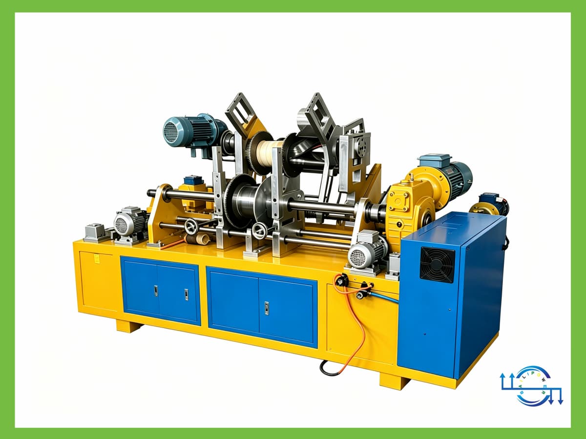
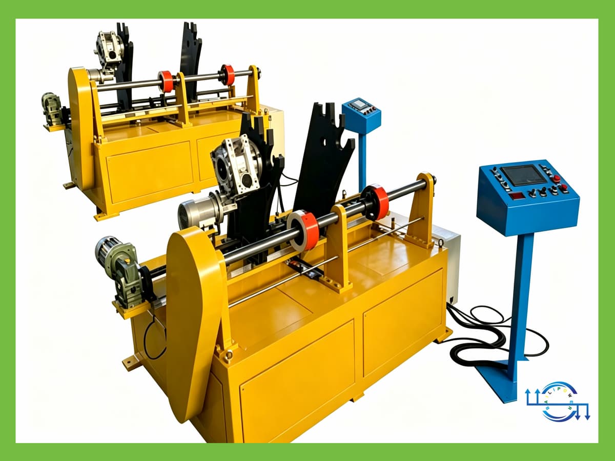
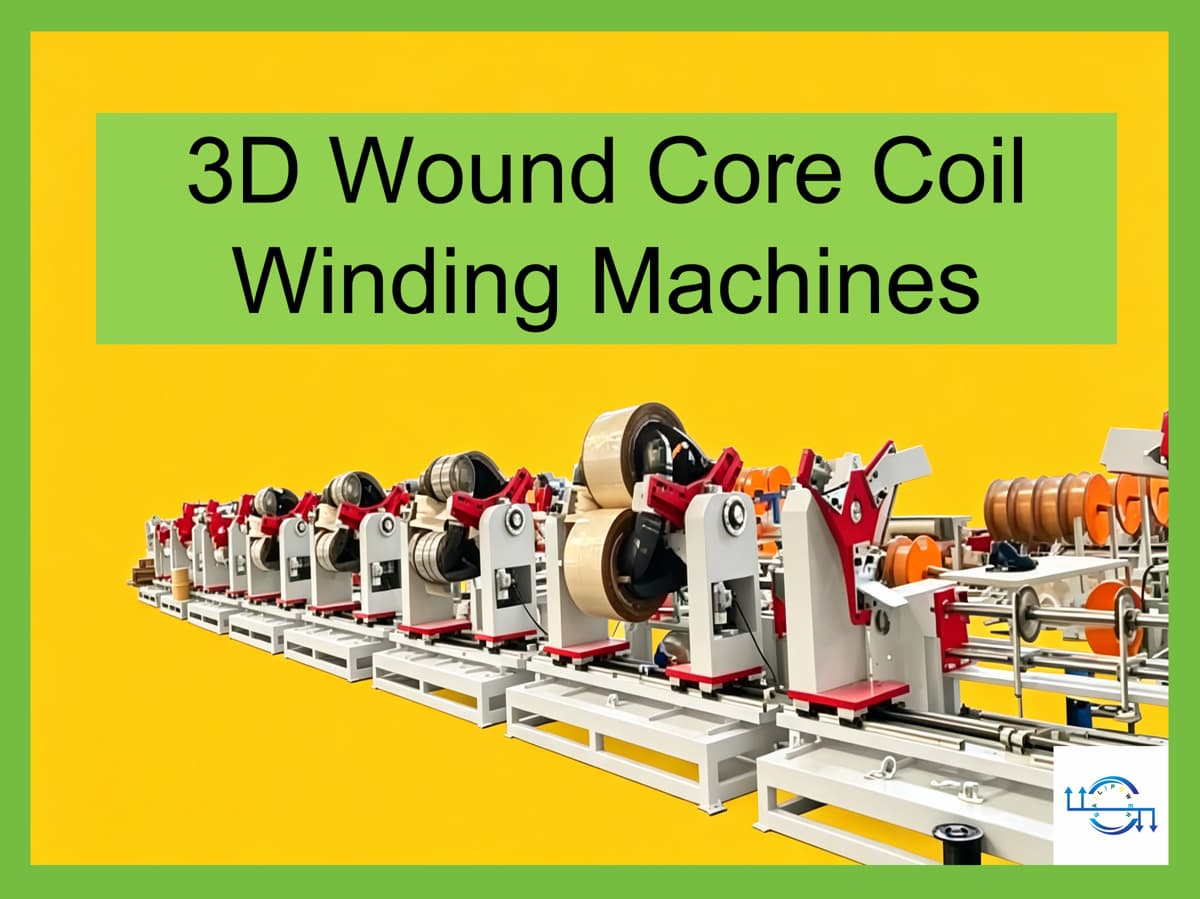
3D Wound Core Coil Winding Machine PCW-820
Bailipower Helps You Choose the Right Winding Machine and Use It More Efficiently
The PCW-820 is a horizontal coil winding machine developed for medium- and large-size 3D wound core transformers.
The model is based on an 820 mm center distance between the three core columns, providing a larger working range than the PCW-630. It is designed for winding copper or aluminum round and flat conductors for 3D wound cores made from silicon steel or amorphous alloy.
PCW-820 provides a maximum load of approximately 3000 kg, rated spindle torque of ≥1800 N·m, and a winding speed of 0–120 r/min with variable-frequency stepless control. It can accommodate flat conductors up to 4 × 14 mm.
For conventional silicon-steel oil-immersed transformer applications, 315–1600 kVA can be used as a reference capacity range. However, transformer capacity alone does not determine machine selection. Actual suitability depends on core geometry, coil dimensions, conductor requirements, load, torque, and the winding process.
Bailipower's approach is to help customers understand these relationships before selecting a winding machine.
1. Why Choose PCW-820?
A winding machine should not be selected by transformer capacity alone.
Two transformers with the same rated kVA can have different coil dimensions because of differences in:
Core material
Core geometry
Voltage level
Insulation system
Cooling method
Frequency
Conductor dimensions
Winding arrangement
Manufacturing requirements
For 3D wound core transformers, the center distance between the three core columns is an important geometric parameter when selecting the winding machine.
For PCW-820, this center distance is 820 mm.
It should be considered together with the maximum coil outside diameter, machine load capacity, spindle torque, clamping range, conductor size, and actual winding requirements.
Do not select a winding machine by kVA alone. Select it according to transformer geometry and actual winding requirements.
2. Designed for Large 3D Wound Core Transformer Coils
PCW-820 adopts a horizontal integrated clamping structure. Three coil workpieces can be mounted on the same dedicated 3D tooling and wound using a consistent positioning reference.
This configuration is designed for the winding requirements of larger 3D wound core transformer coils.
Heavy-Duty Winding Capacity
Key mechanical parameters include:
Maximum load: approximately 3000 kg
Rated spindle torque: ≥1800 N·m
Main motor: 5.5 kW
Winding speed: 0–120 r/min
Speed control: variable-frequency stepless control
Rotation: forward / reverse
Braking: electromagnetic brake and spindle self-locking
For larger winding assemblies, machine selection should consider spindle torque and load capacity together with motor power.
3. Copper and Aluminum Conductors
PCW-820 supports both copper and aluminum conductors, including round and flat wire.
Reference conductor ranges include:
Round wire: Φ0.5–Φ6.0 mm
Flat wire: up to 4 × 14 mm
For larger flat conductors, the actual conductor dimensions, insulation thickness, winding arrangement, and coil drawings should be checked before final machine selection.
Wire-guiding can be configured as manual or automatic follower control according to the machine configuration and production requirements.
4. Multiple Control Options
PCW-820 is available with three main control configurations.
Electronic Counter Control
A practical solution for applications requiring basic winding-speed and turn-count control.
The electronic counter supports:
Forward and reverse counting
Power-off memory
Approx. ±0.1 turn counting error
PLC Control
PLC control provides integrated machine operation and can be configured according to the customer's production requirements.
Servo CNC Control
The servo CNC configuration provides a higher level of automation and can include:
Automatic wire guiding
Servo positioning
Programmable winding control
The reference servo positioning accuracy is approximately ±0.1 mm, depending on the actual machine configuration and operating conditions.
5. Applications
PCW-820 is designed for coil winding applications involving:
Silicon-steel 3D wound core transformers
Amorphous alloy 3D wound core transformers
Oil-immersed transformers
Dry-type transformers
Energy-efficient distribution transformers
Larger-capacity 3D wound core transformer applications
For conventional silicon-steel oil-immersed transformers, 315–1600 kVA can be used as a reference application range.
For amorphous alloy, dry-type, or special transformer designs, the actual coil dimensions and winding requirements should be checked against the machine specifications.
6. Recommended Maximum Coil Outside Diameter: 720 mm
PCW-820 has a theoretical maximum coil outside diameter of approximately 820 mm.
For practical machine selection, Bailipower recommends approximately 720 mm as the maximum working reference.
The theoretical maximum and recommended working range should not be treated as the same value.
Actual production requirements may be affected by:
Conductor dimensions
Insulation thickness
Winding arrangement
Clamping clearance
Dedicated tooling
Operating space
Transformer design
Therefore, the actual coil drawing should be considered when determining whether PCW-820 is suitable for a specific application.
7. Geometry-Based Machine Selection
For 3D wound core transformer applications, a more useful selection method is to start with transformer geometry rather than kVA.
For PCW-820, the main parameters to evaluate are:
7.1 Center Distance Between Three Core Columns
820 mm
This is the key dimension represented by the PCW-820 model designation.
7.2 Maximum Coil Outside Diameter
Theoretical maximum: approximately 820 mm
Recommended maximum: approximately 720 mm
7.3 Maximum Machine Load
Approximately 3000 kg
The load should be evaluated based on the actual coil and tooling assembly.
7.4 Rated Spindle Torque
≥1800 N·m
For larger and heavier winding assemblies, spindle torque is an important selection parameter alongside motor power.
7.5 Conductor and Winding Requirements
The conductor material, conductor dimensions, insulation system, winding arrangement, and wire-guiding requirements should also be considered.
A practical selection sequence is therefore:
Transformer design → Core geometry → Coil dimensions → Load and torque → Conductor → Winding process → Machine configuration
8. What Does the “820” in PCW-820 Mean?
The 820 in PCW-820 refers to the nominal 820 mm center distance between the three core columns of the applicable 3D wound core transformer design.
This dimension is associated with a commonly used 820 mm three-column geometry in the relevant Chinese 10 kV transformer design context.
It should not be interpreted as a universal international transformer standard.
For international projects, the actual transformer design and coil drawings should be used for final machine selection.
9. 315–1600 kVA Reference Application Range
PCW-820 is positioned for larger 3D wound core transformer coil applications.
For conventional silicon-steel oil-immersed transformers, approximately 315–1600 kVA can be used as a reference range.
However, kVA does not directly determine the required winding machine.
For example, transformers with the same rated capacity may require different machines because of differences in:
Core material
Core dimensions
Voltage
Insulation
Cooling method
Conductor size
Coil dimensions
Winding arrangement
Therefore, 1600 kVA should be regarded as a reference application point, not as the definition of PCW-820.
For applications around 30–1000 kVA, PCW-630 may also be considered, depending on the actual transformer geometry.
10. Helping Customers Use Winding Machines More Efficiently
Selecting the correct machine is only one part of transformer coil winding.
Bailipower provides technical support related to machine selection and operation, including:
Winding machine selection
Technical discussion based on transformer drawings
Winding process consultation
Winding parameter setup
Wire-guiding configuration
Machine commissioning
Operator training
After-sales technical support
Customized machine solutions
The purpose is simple: to make the relationship between transformer design, winding requirements, and machine configuration easier to understand and apply.
11. Why Choose Bailipower?
Bailipower's approach is based on four principles:
Science. Reason. Feasibility. Reliability.
A winding machine should be matched to the actual industrial application rather than selected simply because one parameter appears larger.
For 3D wound core transformer production, this means considering the relationship between:
Core geometry → Coil geometry → Load → Torque → Conductor → Winding process → Machine configuration
We believe that a complex industrial machine should be explained clearly enough for customers to make a technically informed selection.
That is also the purpose of Bailipower's technical content: helping customers choose winding machines better and use them more efficiently.
12. Technical Specifications
| Item | PCW-820 Specification |
|---|---|
| Product Name | 3D Wound Core Coil Winding Machine |
| Model | PCW-820 |
| Model Definition | 820 mm center distance between three core columns |
| Application | Winding coils for 3D wound core transformers |
| Spindle Center Height | Approx. 950 mm |
| Conductor | Copper / Aluminum |
| Conductor Type | Round / Flat |
| Round Wire | Φ0.5–Φ6.0 mm |
| Flat Wire | Up to 4 × 14 mm |
| Core Material | Silicon steel / Amorphous alloy wound cores |
| Center Distance | 820 mm |
| Maximum Core Column Diameter | Approx. ≤460 mm, including insulation allowance |
| Maximum Coil Outside Diameter | Approx. 820 mm, theoretical |
| Recommended Maximum Coil OD | Approx. 720 mm |
| Maximum Three-Coil Assembly Diameter | Approx. 1767 mm, theoretical |
| Reference Transformer Capacity | Approx. 315–1600 kVA |
| Maximum Load | Approx. 3000 kg |
| Adjustable Clamping Distance | 600–1400 mm |
| Rated Spindle Torque | ≥1800 N·m |
| Main Motor | 5.5 kW |
| Speed Control | Variable-frequency stepless control |
| Winding Speed | 0–120 r/min |
| Rotation | Forward / Reverse |
| Braking | Electromagnetic brake / spindle self-locking |
| Control Options | Electronic Counter / PLC / Servo CNC |
| Wire Guiding | Manual / Automatic follower |
| Servo Positioning Accuracy | Approx. ±0.1 mm |
| Winding Tension | 0–800 N, continuously adjustable |
| Counting | Encoder counting, forward / reverse |
| Counting Error | Approx. ±0.1 turn |
| Power-Off Memory | Yes |
| Tooling | Dedicated 3D fixture + electric 3-jaw self-centering chuck |
| Dimensions | Approx. 2400 × 1400 × 1550 mm |
| Net Weight | Approx. 2200 kg |
| Noise | ≤82 dB |
| Protection Class | IP54 |
| Power Supply | Customized according to country / region |
The 315–1600 kVA range is a reference application range for conventional silicon-steel oil-immersed transformer designs. Actual suitability depends on transformer drawings, core geometry, coil dimensions, conductor requirements, and winding process.
13. FAQ
13.1 What is the PCW-820?
PCW-820 is a 3D wound core coil winding machine designed for medium- and large-size 3D wound core transformer coil production. The “820” refers to the nominal 820 mm center distance between the three core columns.
13.2 What does the 820 mm center distance mean?
It refers to the geometric center distance between the three core columns in the applicable 3D wound core transformer design. It is one of the key parameters for matching a winding machine to transformer geometry.
13.3 Is PCW-820 a 1600 kVA winding machine?
1600 kVA is a reference application point, not the definition of the machine. Actual suitability depends on transformer geometry, coil dimensions, conductor requirements, load, torque, and winding process.
13.4 What transformer capacity is suitable for PCW-820?
For conventional silicon-steel oil-immersed transformers, approximately 315–1600 kVA can be used as a reference range. Final selection should be based on the actual transformer design and coil drawings.
13.5 Can PCW-820 wind amorphous alloy transformer coils?
Yes. PCW-820 is designed to support winding applications for amorphous alloy 3D wound cores. The actual coil dimensions and winding requirements should be checked for each transformer design.
13.6 Can PCW-820 be used for dry-type transformers?
It can be considered for dry-type 3D wound core transformer applications. Because dry-type transformer construction and insulation requirements can vary, the actual coil drawings should be checked before final machine selection.
13.7 What is the maximum recommended coil outside diameter?
The theoretical maximum coil outside diameter is approximately 820 mm. Bailipower recommends approximately 720 mm as the maximum working reference for practical machine selection.
13.8 What conductors can PCW-820 process?
The machine supports copper and aluminum conductors, including round and flat wire. The reference range includes round wire from Φ0.5 to Φ6.0 mm and flat wire up to 4 × 14 mm.
13.9 What control systems are available?
PCW-820 can be configured with Electronic Counter, PLC, or Servo CNC control. Servo CNC configurations can include automatic wire guiding and servo positioning.
13.10 Can PCW-820 be customized?
Yes. Machine configuration can be discussed according to transformer drawings, conductor dimensions, winding process, control requirements, and production conditions.
13.11 What information should I provide when selecting a winding machine?
Useful information includes transformer capacity, core material, core dimensions, center distance, coil dimensions, conductor type and size, insulation requirements, winding arrangement, and relevant transformer or coil drawings.
13.12 What is the difference between PCW-630 and PCW-820?
The main difference is the applicable three-column center distance.
PCW-630 uses a 630 mm center distance, while PCW-820 uses an 820 mm center distance and provides a larger working range, higher maximum load, and higher rated spindle torque.
The appropriate model should be selected according to the actual transformer geometry rather than capacity alone.