Document Type: Original Engineering Research Paper
Series: BOER (Bailipower Original Engineering Research)
Paper Number: BOER-BM-08
Version: 1.0
Introduction: Why Is Understanding Hardware Not Enough to Understand a Machine?
When selecting a three-station busbar processing machine, buyers usually consider processing capacity, hydraulic systems, control methods, limit switches, foot pedals, and machine price. These are all important factors, but they mainly answer two questions: what components and configurations does the machine use, and what basic requirements can it meet?
There are other questions worth examining.
Why can two three-station busbar machines with similar hardware configurations behave differently during operation? Why does one machine complete a working cycle automatically after a single start command, while another requires the operator to keep the foot pedal depressed? Why can forward motion use different stopping or return responses? How do upper-limit and lower-limit switch configurations affect machine-state feedback and control decisions?
These questions cannot be answered by comparing component lists or machine specifications alone. We also need to understand the relationships among mechanical motion, state feedback, operator input, and the control system.
This is the starting point of Bailipower's BOER-BM Series research into the control logic of three-station busbar machines.
From BOER-BM-01 through BOER-BM-07, the series examines typical control logic configurations, the engineering reasons behind different configurations, the role of limit switches, foot-pedal control and human-machine interaction, and the differences between Class A and Class B control logic.
Together, these studies lead to a more fundamental question:
Why does a machine behave in a particular way, and what determines its actual behavior?
1. From Seven Research Articles to an Engineering Analysis Framework
The BM Series does not simply list different control configurations. It starts with observable machine motion and progressively examines how control logic is formed, implemented, and translated into actual operating behavior.
| Research article | Research topic | Main engineering question |
|---|---|---|
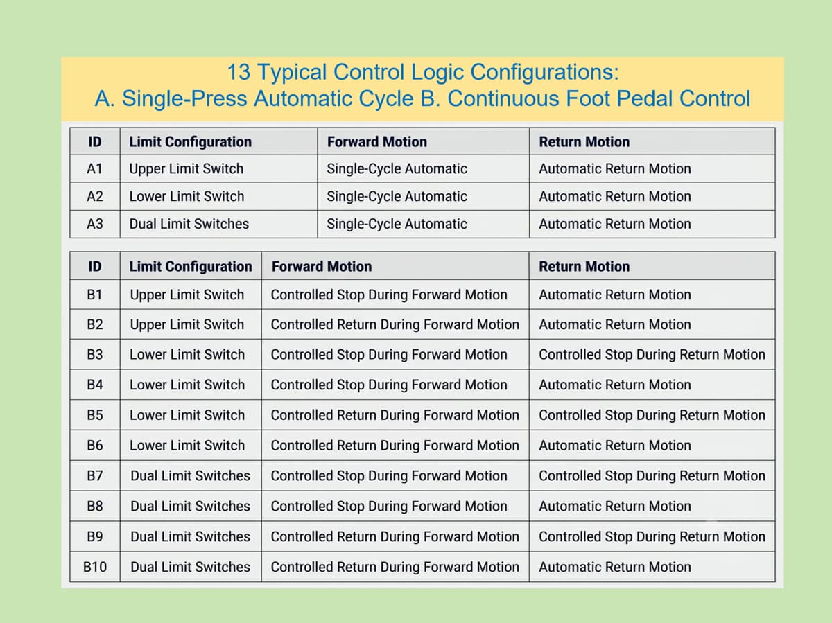
| BOER-BM-01 | Classification of typical control logic configurations | How can different configurations be systematically classified by their motion processes? |
| BOER-BM-02 | Why different control logic configurations exist | Why do different machines adopt different control solutions? |
| BOER-BM-03 | Limit-switch configurations and motion control | What information can upper-limit, lower-limit, and dual-limit feedback provide? |
| BOER-BM-04 | Foot-pedal control and human-machine interaction | How does the operator participate in machine motion, and how does the machine respond? |
| BOER-BM-05 | Class A single-cycle automatic control: A1, A2, and A3 | How do different limit-switch configurations affect single-cycle automatic control? |
| BOER-BM-06 | Class B continuous foot-pedal control: B1–B6 | How does continuous operator input interact with forward motion, stopping, and return? |
| BOER-BM-07 | Class B dual-limit control: B7–B10 | How are dual-limit feedback and different motion responses combined? |
BM-01 establishes the classification method. Instead of classifying machines primarily by PLC brand, hydraulic components, or electrical configuration, it focuses on what the machine actually does, how it responds, and how forward and return motion are controlled.
BM-02 examines why different configurations exist. Control solutions may reflect different priorities involving safety, production efficiency, operating convenience, manufacturing cost, available control technology, and market requirements. They are engineering choices made to meet different objectives, not an automatic ranking from best to worst.
BM-03 and BM-04 extend the analysis to two essential parts of machine control: how the machine receives information about its state and how the operator provides control input.
BM-05 through BM-07 apply this framework to specific Class A single-cycle automatic configurations and Class B continuous foot-pedal configurations.
Together, the seven articles form a progressive research path:
Motion-process classification → Engineering objectives → State feedback → Human-machine interaction → Configuration analysis → Practical engineering evaluation.
The value of this approach is that it separates hardware, operator input, feedback, and machine behavior before examining how they work together.
2. Hardware Is the Physical Shell; Control Logic Is the Machine's Mind
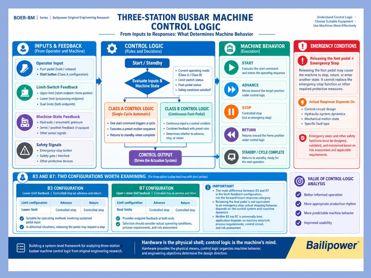
Hardware is the physical shell; control logic is the machine's mind.
This is a central engineering idea behind the BOER-BM Series.
The terms physical shell and mind are metaphors. They do not suggest that mechanical, hydraulic, or electrical hardware is unimportant. Rather, they emphasize that knowing a machine's components is not the same as understanding how it operates.
The mechanical structure establishes the physical conditions for motion and load-bearing. The hydraulic system provides the required power and motion capability. Electrical and sensing components provide signal acquisition and actuation interfaces. Foot pedals and push buttons provide operator input, while limit switches provide position-related feedback.
Control logic organizes these inputs, feedback signals, and action requirements into rules that determine how the machine responds under different conditions.
For example, when an operator presses a foot pedal, the machine does not necessarily execute one fixed action simply because it has received an input signal. Its response depends on the current operating state, the configured control logic, relevant feedback signals, and whether the mechanical and hydraulic systems can perform the required action.
Similarly, when the operator releases the foot pedal, the machine may stop its current motion, continue a predefined sequence, or enter another control state. The actual response depends on the machine's control design. It cannot be determined from the term foot-pedal control alone.
This also explains why component count is not a reliable measure of control quality.
Two machines may both use PLC control and have hydraulic systems and foot pedals, yet differ in their forward-motion response, return behavior, degree of operator involvement, and use of position feedback.
Conversely, even well-designed control logic cannot compensate for insufficient structural strength, inadequate hydraulic capacity, unsuitable electrical configuration, or missing safety measures.
A more complete engineering perspective is therefore:
Hardware provides the physical means, control logic organizes machine behavior, and engineering objectives determine the design direction.
Understanding a machine requires examining these factors together rather than focusing on any one of them in isolation.
3. Control Logic Is Not Another Name for a PLC
In industrial machinery discussions, control logic, the control system, and the PLC are sometimes treated as if they were the same thing. However, they represent different layers of machine design.
Control logic describes how the machine should operate: under what conditions it starts, when it stops, whether it returns, and how operator inputs relate to machine-state feedback.
The control system implements these rules. A PLC can be one part of that implementation, but control logic itself is not synonymous with a PLC.
Their relationship can be summarized as follows:
Engineering objectives → Control logic configuration → Control system implementation → Actual machine behavior.
For example, an engineering requirement may call for the operator to participate in motion through continuous input, while the control system responds to changes in that input and to machine-state feedback. The designer must first define the motion process, feedback conditions, and response rules, then implement them through suitable electrical controls, hydraulic circuits, and mechanical actuators.
Starting a design discussion with the question "Which PLC should we use?" without first defining the required machine behavior can confuse the implementation method with the design objective.
At the same time, control logic cannot be designed independently of the hardware. Actuator response, hydraulic dynamics, mechanical inertia, and feedback-device performance all affect what the control system can achieve in practice.
A complete engineering process must therefore define the control logic and verify that the control system, mechanical structure, and hydraulic system can implement it reliably.
4. The Role of Limit Switches: Providing Feedback, Not Independently Deciding Machine Actions
One important conclusion of BM-03 is that limit-switch configuration should not be treated simply as a question of component count.
In a three-station busbar machine, an upper-limit switch commonly provides feedback about the return endpoint or home position, while a lower-limit switch commonly provides feedback about the processing endpoint. A dual-limit configuration can provide position-related information at both endpoints.
However, a limit switch does not independently decide whether the machine should stop, return, or continue moving. It provides a signal. The control logic determines how that signal is interpreted and what response follows, together with any other relevant conditions.
The process can be represented as:
Machine motion → Limit-switch feedback → Control logic decision → Actuator response → New machine state.
This sequence is fundamental to understanding different control configurations.
For example, a lower-limit switch alone does not directly provide position feedback at the return endpoint. Upper- and lower-limit switches can provide feedback at both endpoints, but this does not automatically constitute continuous closed-loop position control.
A dual-limit configuration also cannot, by itself, guarantee higher machining accuracy. Actual results depend on factors such as mechanical rigidity, tooling condition, limit-switch repeatability, hydraulic dynamics, machine adjustment, and maintenance.
More limit switches do not necessarily make a machine better. Additional feedback devices may support more control options, but they can also introduce additional wiring, commissioning, maintenance, and cost requirements.
The key questions are whether the feedback serves a defined engineering purpose and whether the control system uses it appropriately.
This reflects a basic principle of the BM Series:
Define which machine states need to be identified before deciding what feedback hardware is required.
5. Class A and Class B Control Logic: Different Operating Modes, Different Levels of Operator Involvement
BM-05 through BM-07 examine Class A and Class B control logic in greater detail.
The basic principle of Class A single-cycle automatic control is that the operator issues a start command, after which the machine executes a predefined cycle and enters its designated state when the cycle is complete.
Class B continuous foot-pedal control follows a different approach. The operator maintains an input, and the control system uses that input together with machine-state feedback and predefined rules to determine whether motion continues, stops, or returns.
The difference is not simply a matter of whether one machine is more automated than another. It also concerns how motion-control participation is distributed between the operator and the machine.
5.1 Class A: One Start Command, a Predefined Automatic Cycle
A1, A2, and A3 are all Class A single-cycle automatic configurations, but they use different limit-switch arrangements:
A1: Upper-limit configuration.
A2: Lower-limit configuration.
A3: Dual-limit configuration.
All three are based on a single start command followed by an automatic cycle. However, their available endpoint feedback differs, which may affect how endpoint states and return behavior are handled in the actual control implementation.
Limit-switch configuration alone does not define every detail of the control sequence. The actual behavior also depends on the electrical circuit, programmed rules, and the stopping and return methods used by the machine.
5.2 Class B: Continuous Input and Ongoing Control Response
Class B configurations B1–B10 are based on continuous foot-pedal input.
B1–B6 use upper-limit or lower-limit configurations, while B7–B10 use dual-limit feedback. These arrangements are combined with different forward-motion responses, such as controlled stop or controlled return, and different return responses, such as controlled stop or automatic return.
The differences among B7–B10 can be summarized as follows:
| Configuration | Limit feedback | Forward-motion response | Return response |
|---|---|---|---|
| B7 | Upper and lower limits | Controlled stop | Controlled stop |
| B8 | Upper and lower limits | Controlled stop | Automatic return |
| B9 | Upper and lower limits | Controlled return | Controlled stop |
| B10 | Upper and lower limits | Controlled return | Automatic return |
Controlled stop, controlled return, and automatic return describe machine motion responses. Their exact meaning and implementation depend on the actual control design. The labels alone do not guarantee identical behavior across different machines.
In Class B control, continuous operator input is an important part of the control process. However, the relationship between the foot-pedal signal, limit-switch feedback, and actual machine motion is not necessarily a simple one-to-one relationship. How the machine responds to a change in input depends on its specific control logic.
When evaluating Class A and Class B solutions, buyers should therefore consider more than the level of automation. Production cycle, operating habits, processing requirements, abnormal-response behavior, machine cost, and maintenance requirements are also relevant.
6. Why Are B3 and B7 Worth Examining in Real Production?
Within this classification framework, B3 and B7 deserve closer examination.
B3 uses lower-limit feedback, with controlled stop during both forward and return motion. B7 uses upper- and lower-limit feedback, also with controlled stop during both forward and return motion.
Their motion-response categories are similar. The main difference is the endpoint feedback configuration.
For three-station busbar machines with relatively short strokes, these configurations may offer useful ways to study the relationship between continuous operator input and machine motion. The operator remains involved in the operating process, while the control system responds according to predefined rules and relevant machine-state signals.
This deserves consideration in real production environments.
6.1 Natural Operator Reactions Are Part of Human-Machine Engineering
Machine safety design must consider not only control circuits but also operator behavior under real working conditions.
During an unexpected event, an operator may instinctively release the foot pedal rather than immediately locate and press the emergency-stop button. In some continuous foot-pedal control arrangements, releasing the pedal may be a more direct operator action.
Rather than treating this only as an operating habit, it can be examined as a human-machine engineering question:
What does the machine actually do when the operator releases the foot pedal?
What control steps occur between the input change and the machine's stopping response?
How do mechanical inertia, hydraulic dynamics, and machine structure affect the stopping process?
Can the operator recognize an abnormal condition and respond appropriately from the normal operating position?
These questions are more closely related to real production than simply comparing the number of buttons or the nominal level of automation.
6.2 Releasing the Foot Pedal Is Not a Substitute for Emergency Stop
An important boundary must be made clear: releasing the foot pedal is not the same as activating the emergency stop, and it should not automatically be regarded as a validated safety function.
Different control circuits may respond differently when the pedal is released. Even when the control logic calls for motion to stop, the hydraulic system and mechanical structure may introduce response time, inertia, or other dynamic effects.
It is therefore not appropriate to claim universally that releasing a foot pedal is faster or safer than pressing an emergency-stop button.
Emergency-stop functions and other required protective measures must be determined, implemented, verified, and maintained according to the machine's risk assessment, applicable requirements, and actual control design. A limit switch does not automatically qualify as a safety-rated protective device simply because it participates in machine control.
The engineering value of examining B3 and B7 is that they highlight an important point: control logic affects not only how a machine completes its processing cycle, but also how the operator participates in motion and how the machine responds under abnormal conditions.
6.3 B3 and B7 Are Not Universally the Best Solutions
B3 uses lower-limit feedback only, whereas B7 uses both upper- and lower-limit feedback. Their available endpoint information differs, so their suitability must be evaluated against the actual machine design and operating requirements.
If an application requires feedback at both the processing endpoint and the return endpoint, a dual-limit configuration may be more appropriate. In other applications, additional feedback devices may provide limited practical benefit relative to their cost, complexity, or maintenance requirements.
Likewise, controlled stopping in both forward and return motion does not, by itself, prove that a configuration provides higher machining accuracy or a higher level of safety.
A more reasonable conclusion is that B3 and B7 are useful configurations to examine when studying control logic and selecting three-station busbar machines. They should not be presented as universal solutions for every operating condition.
7. Can the Analysis Method Be Applied to Other Industrial Machines?
The specific classifications and conclusions in the BM Series primarily address the motion characteristics and typical operating scenarios of three-station busbar machines.
Other machines may have different travel distances, inertia, actuators, production cycles, and operating methods. For example, long-stroke or high-inertia equipment may involve more complex stopping distances, stored energy, and workpiece movement. Depending on the machine design, releasing an operator input may need to trigger a specific deceleration, braking, or safety response.
The control strategies used for a short-stroke busbar machine therefore cannot simply be transferred to another machine and assumed to be the best solution.
However, the BM Series provides an analytical approach that can serve as a reference for studying other industrial equipment.
7.1 Define the Engineering Objectives
First, determine what the machine must accomplish and identify the relevant requirements for production efficiency, operating convenience, manufacturing cost, maintenance capability, and safety.
Different engineering objectives may lead to different appropriate control solutions.
7.2 Describe the Actual Motion Process
Analyze the machine's working cycle and identify its actual states, such as starting, forward motion, processing, stopping, return, and standby. Determine the conditions that cause transitions between these states.
Do not infer machine behavior from the equipment name or component configuration alone.
7.3 Distinguish Operator Input from Machine-State Feedback
Foot pedals and push buttons provide operator input. Limit switches and other sensing devices provide information about machine state. These signals serve different purposes.
The analysis should identify who or what generates each signal, how the machine determines its current state, and which conditions the control system uses to select a response.
7.4 Analyze Control Logic and Physical Implementation
Determine which response follows from each relevant input or feedback condition. Then verify whether the mechanical, hydraulic, and electrical systems can implement that response under the required operating conditions.
Control logic must be feasible within the physical capabilities of the actual machine.
7.5 Verify Abnormal Responses and Safety Measures
A machine that completes its normal working cycle correctly is not necessarily safe under every possible condition.
The analysis should also consider abnormal states, stopping behavior, residual motion, and required protective measures. These must be evaluated and verified according to the applicable requirements and the machine's risk assessment.
7.6 Evaluate the Solution Under Actual Operating Conditions
Finally, compare the available solutions in terms of production efficiency, operating convenience, manufacturing cost, maintenance requirements, and safety.
The analysis method can be adapted, but each specific solution must be evaluated against the machine and its operating conditions.
This is both a boundary of the BM Series and an important part of its engineering value.
8. How Can Manufacturers and Users Benefit from Control Logic Research?
Control logic analysis is not only for machine designers. It also has practical value for equipment manufacturers, buyers, and operators.
8.1 For Machine Manufacturers
Control logic research helps designers define motion processes, feedback requirements, and operator involvement at an early stage, rather than deciding on control configurations only after the mechanical and hydraulic designs have been established.
It also helps manufacturers explain why a particular solution was selected, reducing reliance on comparisons based only on component count, brand names, or automation labels.
8.2 For Equipment Buyers
Buyers can move beyond questions such as "Which PLC does this machine use?" or "How many limit switches does it have?" and ask more meaningful engineering questions:
How does the machine stop or return during forward and return motion?
What control decisions use the limit-switch feedback?
Which operations require continuous operator involvement?
How do normal stopping and emergency stopping differ on this machine?
Are these control methods suitable for the intended production cycle, processing requirements, and operating environment?
These questions provide a more complete basis for evaluating whether a machine fits the actual application.
8.3 For Machine Operators
Understanding control logic helps operators better understand normal operating sequences, machine-state changes, and the purpose of different control inputs.
However, understanding control logic does not replace operator training, maintenance procedures, or safety rules. Changes to control circuits, hydraulic systems, or safety functions should be made only by appropriately qualified personnel in accordance with the machine design and applicable requirements.
A machine's value lies not only in the processing tasks it can perform, but also in whether its manufacturer can clearly explain how it operates and whether users can understand and operate it correctly.
9. Conclusion: Understand Machines Better to Choose and Use Them Better
The BOER-BM Series starts with three-station busbar machines and examines typical control logic configurations, the engineering reasons behind different solutions, limit-switch feedback, foot-pedal control and human-machine interaction, and the specific differences between Class A and Class B control methods.
The purpose is not to prove that one configuration is always the best, nor to increase control-system complexity for its own sake. It is to establish a clearer engineering understanding of machine behavior.
Actual machine behavior is not determined by a single limit switch, a particular PLC, or an individual hydraulic component. It emerges from the interaction of engineering objectives, mechanical structure, hydraulic capability, electrical configuration, operator input, state feedback, and control logic.
Hardware is the physical shell; control logic is the machine's mind.
Hardware establishes the physical conditions under which the machine can operate. Control logic organizes how the machine responds under different conditions. Engineering objectives determine how these capabilities should be combined and applied.
For manufacturers, understanding these relationships supports more rational machine design. For buyers, it helps clarify technical requirements and evaluate equipment. For operators, it supports a better understanding of machine operation and appropriate use.
This is the purpose of Bailipower's BM engineering research:
Bailipower helps people choose machines better and use machines better.
We follow the principles of science, reason, feasibility, and reliability—manufacturing machines adapted to real industrial working conditions, with a thoughtful approach to industrial engineering and design.
10. Frequently Asked Questions
10.1 What Is Punching and Shearing Control Logic in a Three-Station Busbar Machine?
Punching and shearing control logic defines how a three-station busbar machine responds to operator inputs, limit-switch signals, and predefined control rules. It determines when the machine starts, moves forward, stops, returns, or enters another operating state. It is therefore about the machine's behavior under different conditions, not simply which PLC it uses or how many limit switches are installed.
10.2 What Is the Difference Between Control Logic and a PLC?
Control logic describes how a machine should operate, while a PLC is one type of control device that can implement those rules. Control logic defines the intended machine behavior; the PLC belongs to the implementation layer of the control system. Two machines using the same type of PLC may still have different control logic and operating behavior.
10.3 Are More Limit Switches Always Better for a Three-Station Busbar Machine?
No. An upper-limit switch commonly provides feedback about the return endpoint or home position, while a lower-limit switch commonly provides feedback about the processing endpoint. A dual-limit configuration provides position-related feedback at both endpoints. However, additional switches also introduce wiring, commissioning, maintenance, and cost considerations. The appropriate configuration depends on the motion process, feedback requirements, control logic, and safety design—not simply on the number of switches.
10.4 Does Dual-Limit Feedback Mean That a Busbar Machine Has Closed-Loop Control?
No. Upper- and lower-limit switches can provide endpoint feedback, but this does not automatically constitute continuous closed-loop position control. Determining whether a machine uses closed-loop control requires examining its measurement, feedback-processing, and control-adjustment mechanisms. The number of limit switches alone is not enough to establish this.
10.5 What Is the Difference Between Class A and Class B Control Logic?
Class A single-cycle automatic control is typically triggered by one start command, after which the machine follows a predefined cycle. Class B continuous foot-pedal control incorporates the operator's maintained input into the motion-control process. The control system responds according to that input, machine-state feedback, and predefined rules. The main difference lies in the organization of operator input and machine response; the exact behavior depends on the actual control design.
10.6 Why Are B3 and B7 Worth Considering?
B3 uses lower-limit feedback, with controlled stop during both forward and return motion. B7 uses upper- and lower-limit feedback, with the same forward and return response categories. Their main difference is the endpoint feedback configuration. For short-stroke three-station busbar machines, these configurations are worth evaluating in relation to operator involvement, production cycle, and actual working conditions. This does not mean they are suitable for every application or inherently better than other configurations.
10.7 Does a Three-Station Busbar Machine Stop Immediately When the Foot Pedal Is Released?
Not necessarily. The response to pedal release depends on the control circuit, control logic, and dynamic characteristics of the mechanical and hydraulic systems. Releasing the foot pedal is not equivalent to activating the emergency stop and cannot replace required emergency-stop or other protective functions. Users should confirm the actual response from the machine documentation, control design, and applicable safety requirements.
10.8 Can the BOER-BM Series Control Logic Analysis Method Be Applied to Other Industrial Machines?
It can provide a useful analytical reference, but the specific control configurations and conclusions developed for three-station busbar machines should not be transferred directly to other equipment. Machines may differ in travel distance, inertia, stopping distance, actuators, process requirements, and safety conditions. Each application requires its own analysis of engineering objectives, motion processes, operator input, state feedback, control responses, and safety requirements.
10.9 Why Should Buyers Look Beyond Specifications and Hardware When Selecting a Machine?
Specifications and hardware configurations are important, but they do not fully describe how a machine behaves in production. Buyers should also understand its starting method, forward and return control, state feedback, operator involvement, abnormal-response behavior, and maintenance requirements. Evaluating these factors alongside the processing requirements and production environment provides a more complete basis for equipment selection.
10.10 What Is the Purpose of the BOER-BM Series Research?
The BM Series aims to help machine manufacturers, buyers, and operators better understand the control logic of three-station busbar machines and its engineering significance. Rather than simply comparing component counts or automation labels, it examines the relationships among engineering objectives, operator input, machine-state feedback, and actual machine behavior. The goal is to support more informed machine design, selection, and use.
10.11 Is It Necessary to Consider Punching and Shearing Control Logic When Buying a Three-Station Busbar Machine?
The importance of punching and shearing control logic depends on the processing requirements and operating conditions. If the application only requires basic punching and shearing, buyers may not need to focus heavily on control-logic differences, provided the selected machine meets the necessary processing and safety requirements.
Bailipower's recommendation is to pay closer attention to control logic when production efficiency, operating experience, operator interaction, and flexible operating methods are important. Whether the machine completes a predefined cycle after a start command or requires continuous foot-pedal input can significantly affect the workflow and the operator's daily experience.
These differences should be evaluated against the machine's actual control design and verified safety functions, rather than assuming that one operating mode is universally more efficient or safer.
Ultimately, the right choice is the one that fits the real production process.
Bailipower — helping people choose machines better and use machines better.