Previous
Next
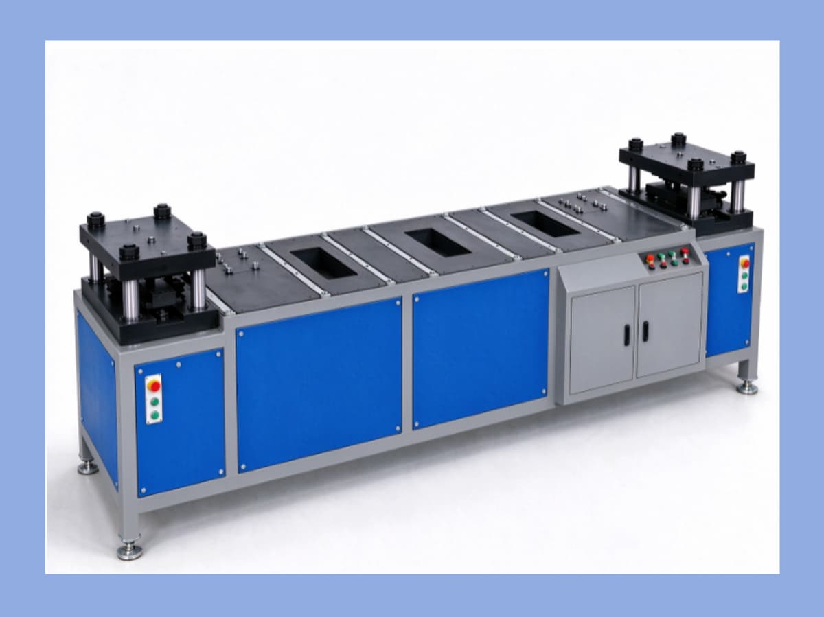
Double-Head Busbar Bending Machine PBM-600DB
600 kN-Class Double-Head Hydraulic Bending for Busbar End Forming
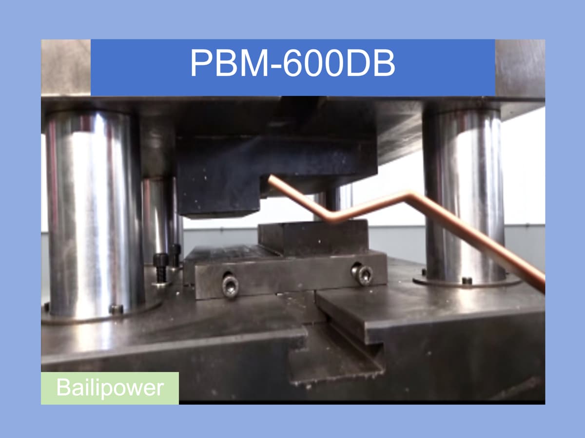
The PBM-600DB Double-Head Busbar Bending Machine is designed for busbar end bending and step forming. It is suitable for busbar duct systems, power distribution equipment, and other industrial applications that require busbar end forming.
The machine uses two independent hydraulic bending heads, dual motors and pumps, and two independent hydraulic valve groups. It supports both synchronized double-head bending and independent single-head operation.
However, for this type of machine, simply looking at a specification such as 600 kN is not enough.
What does the machine actually control? And what does the tooling determine?
Understanding these questions helps customers choose the right machine more rationally and use it correctly.
1. What Type of Busbar Bending Method Does the PBM-600DB Use?
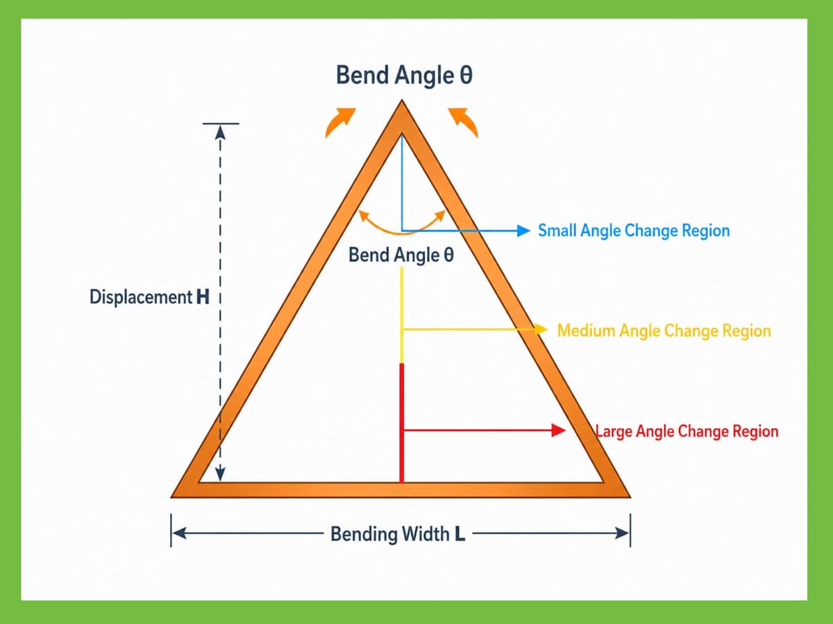
From the perspective of mechanical motion and mathematical relationships, busbar bending can be understood through three fundamental methods:
Angle-Constrained Bending
Angle-Controlled Bending
Displacement-Controlled Bending
In our previous analysis of busbar bending methods, the basic relationship of Angle-Constrained Bending can be simplified as:
θ = f(θd)
where:
θ = final forming angle
θd = angular constraint determined by the tooling geometry
In other words:
Tooling Geometry → Final Forming Angle
This is different from a typical three-station CNC busbar processing machine, where the bending die displacement is controlled to indirectly generate the required bending angle.
For the forming method used by the PBM-600DB, the basic principle can be understood simply as:
The machine provides the force and motion; the tooling determines the forming geometry.
2. Why Is the Forming Angle Mainly Determined by the Tooling?
In Angle-Constrained Bending, the main function of the machine is to provide sufficient force and complete the bending movement through its mechanical structure.
The final forming angle and geometry are mainly determined by the geometry of the tooling.
Therefore, unlike a rotary angle-control mechanism, the machine does not directly input and control a rotational angle such as 90° or 45°.
The process can be understood more accurately as:
Tooling Geometry → Mechanical Constraint → Busbar Forming Result
Therefore, when the end structure of a product changes and a different forming geometry is required, the corresponding tooling normally needs to be changed or adjusted according to the product requirements.
This is why selecting this type of machine should not be based only on maximum bending force. The tooling solution and the actual product geometry are equally important.
3. What Is the PBM-600DB Mainly Used For?
The PBM-600DB is mainly designed for busbar end bending and step forming.
For example, in busbar duct systems and related electrical connection structures, the end of a busbar may need to be formed with a specific step height to meet the requirements of male and female joint structures or other connection designs.
One point should be clearly understood:
The maximum bending height of 30 mm refers mainly to the step height formed at the busbar end. It is not the “bending height” of a conventional 90° busbar bend.
Therefore, when selecting the machine, customers should confirm the actual product drawings, including:
Busbar width
Busbar thickness
Busbar length
Whether both ends require forming
Required end step height
Forming positions and geometry at both ends
Whether multiple product specifications are involved
These factors are more meaningful for machine selection than simply comparing maximum bending force.
4. Why Does the PBM-600DB Use a Double-Head Structure?
The PBM-600DB uses two independent hydraulic bending heads on the left and right sides.
The machine supports:
Synchronized double-head bending
and:
Independent left- or right-head operation
The main purpose of the double-head structure is to process products that require forming at both ends of a long busbar, helping reduce repeated turning, repositioning, and alignment operations.
For busbars with a maximum length of 6000 mm, the overall machine layout and operating method become particularly important when both ends need to be processed.
Therefore, the key question when choosing a double-head machine is not:
“Is a double-head machine better than a single-head machine?”
The more useful question is:
“Does my product actually require forming at both ends?”
If both ends need to be processed regularly, the value of the double-head structure becomes much clearer.
5. What Does 600 kN Mean?
The rated bending force of the PBM-600DB is:
600 kN per head
The 600 kN specification refers to the rated bending force of one hydraulic bending head.
When both heads operate simultaneously, each bending head performs its respective forming operation.
Machine selection should not simply be based on the idea that “higher force is always better.”
The required bending force should be considered together with:
Busbar material
Busbar width
Busbar thickness
Tooling geometry
Forming height
Forming method
Actual production requirements
This reflects an important principle of Bailipower:
Machine selection should first match the process, rather than simply compare specifications.
6. Hydraulic System of the PBM-600DB
The PBM-600DB uses:
Dual motors + dual pumps + two independent hydraulic valve groups
The left and right bending heads have relatively independent hydraulic drive systems.
This configuration corresponds to the double-head working structure and supports:
Synchronized double-head bending
Left-head independent operation
Right-head independent operation
Separate operation of the two sides
The maximum hydraulic working pressure is:
25 MPa
The effective cylinder stroke is:
80 mm
Main motor power:
5.5 kW
7. Why Does the Worktable Use a Roller Structure?
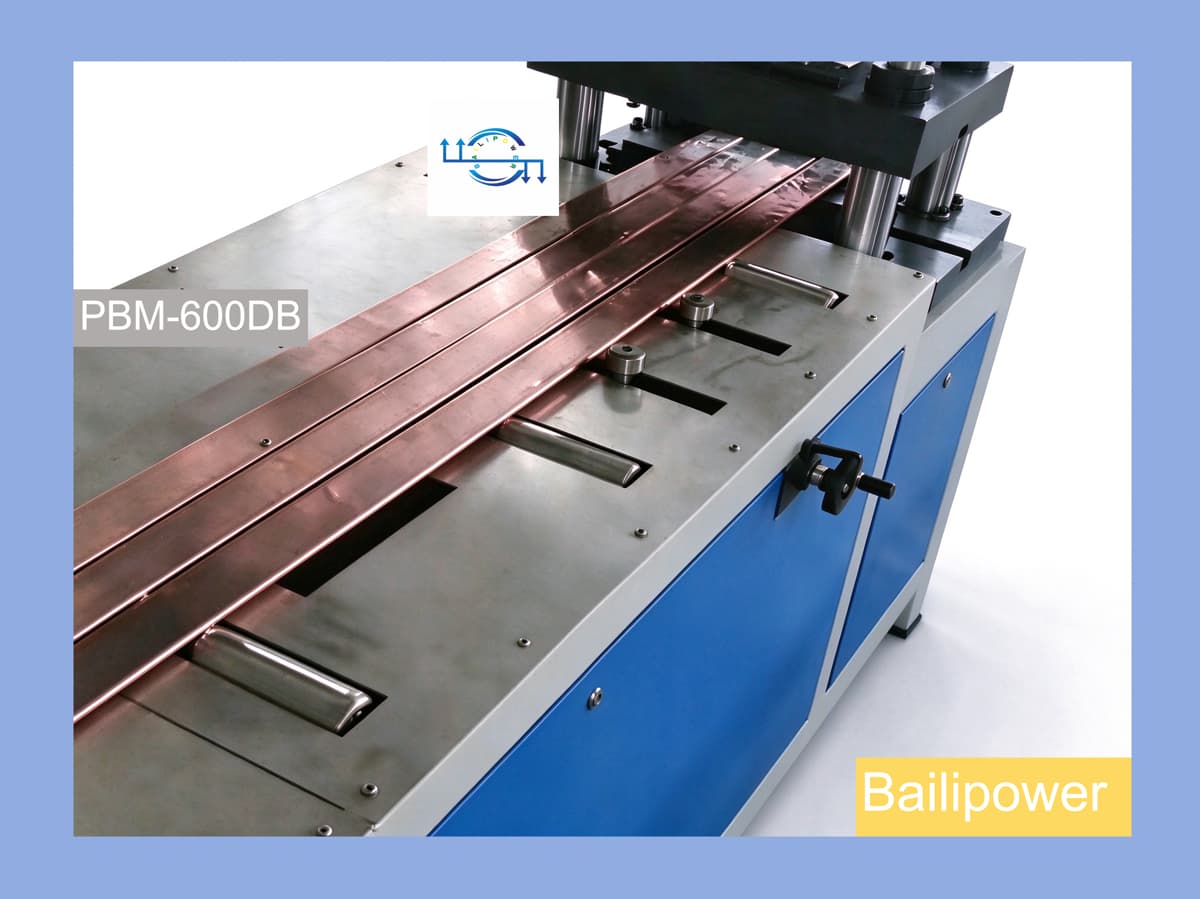
The PBM-600DB worktable uses:
Stainless steel surface + load-bearing rollers + side positioning stops
For busbars up to 6000 mm long, workpiece weight and handling can directly affect the actual operating process.
The load-bearing rollers help reduce sliding resistance, making it easier to move and position long busbars on the worktable.
The side positioning stops assist with workpiece positioning.
This design is not intended simply to make the machine look more sophisticated. It is designed around practical requirements in an industrial working environment.
This also reflects Bailipower's approach to machine design:
We manufacture machines adapted to real industrial environments, rather than machines designed only to look attractive.
8. Relay Control and PLC Control
The PBM-600DB provides two control options:
Relay Control
PLC Control
For applications with relatively straightforward machine movements and stable processing requirements, relay control can meet basic operating needs.
If the customer requires more complex motion sequences, different product programs, or future automation integration, PLC control can be selected according to the actual production requirements.
Therefore, the control method should not simply be understood as:
“PLC is always better than relay control.”
A more useful question is:
“What type of control does the current product and production process actually require?”
This is also part of selecting a machine rationally.
9. PBM-600DB Technical Specifications
| Item | Specification |
|---|---|
| Model | PBM-600DB |
| Machine Name | Double-Head Busbar Bending Machine |
| Rated Bending Force | 600 kN / head |
| Main Motor Power | 5.5 kW |
| Effective Cylinder Stroke | 80 mm |
| Maximum Hydraulic Working Pressure | 25 MPa |
| Processing Material | Copper / Aluminum Busbar |
| Maximum Busbar Size | 6000 × 260 × 7 mm (L × W × T) |
| Minimum Busbar Size | 30 × 3 mm (W × T) |
| Maximum Forming Height | 30 mm |
| Working Mode | Synchronized double-head bending / independent single-head operation |
| Control | Relay Control / PLC Control optional |
| Hydraulic System | Dual motors and pumps, two independent hydraulic valve groups |
| Bending Structure | Two independent hydraulic bending heads, three-beam four-column guiding structure |
| Worktable | Stainless steel surface + load-bearing rollers + side positioning stops |
| Safety Protection | Emergency stop buttons on both sides, hydraulic overload protection |
| Power Supply | Voltage and Frequency Customized to Local Requirements |
| Machine Dimensions | Approx. 5500 × 980 × 1000 mm (L × W × H) |
10. How to Choose the PBM-600DB
Before selecting a double-head busbar bending machine, we recommend confirming the following questions.
10.1 Does the Product Require Busbar End Step Forming?
If the application only requires a conventional 90° busbar bend, first confirm whether the actual forming process is suitable for this type of Angle-Constrained Bending.
10.2 What Is the Maximum Busbar Size?
The key dimensions are:
Length × Width × Thickness
The maximum processing size of the PBM-600DB is:
6000 × 260 × 7 mm
The minimum busbar size is:
30 × 3 mm
10.3 Do Both Ends of the Busbar Require Processing?
If both ends regularly require forming, the double-head structure becomes more relevant.
If only one end is normally processed, the actual production requirements should be compared between single-head and double-head solutions.
10.4 What Is the Required End Step Height?
The maximum forming height of the PBM-600DB is:
30 mm
The actual product drawing should be checked to confirm the required forming height and tooling geometry.
10.5 How Frequently Do Product Specifications Change?
If product specifications are relatively stable, the machine can be designed around a relatively fixed tooling solution.
If product specifications change frequently, customers should consider tooling changeover, adjustment requirements, and the control system when selecting the machine.
11. Helping Customers Choose Machines More Effectively
For industrial machinery, whether a machine is suitable cannot be determined by a single specification.
Force, dimensions, structure, tooling, control method, and the actual manufacturing process form one complete system.
Therefore, Bailipower aims to do more than simply tell customers:
“These are the specifications of the machine.”
More importantly, we want to help customers understand:
“Why is the machine designed this way?”
and:
“What type of product is this machine actually suitable for?”
This is an important direction for Bailipower:
Helping customers choose machines better, and helping customers use machines better.
12. Bailipower's Machine Design Philosophy
For the PBM-600DB, we focus on whether the machine can genuinely adapt to real industrial working conditions.
Scientific — Based on actual processes and mechanical principles.
Reasonable — Matching machine structure and functions to actual requirements.
Feasible — Ensuring that the technical solution can be implemented in real production.
Reliable — Building machines for long-term use in industrial production.
This is also part of the equipment philosophy that Bailipower aims to follow:
Manufacturing machines adapted to real industrial environments, and manufacturing machines with a sense of industrial culture and quality.
13. Frequently Asked Questions
13.1 What is the PBM-600DB?
The PBM-600DB is Bailipower's Double-Head Busbar Bending Machine, mainly designed for busbar end bending and step forming.
It uses two independent hydraulic bending heads and supports synchronized double-head bending as well as independent operation of either side.
13.2 What is the maximum bending force of the PBM-600DB?
The rated bending force is 600 kN per head.
The actual required bending force should also be considered together with the busbar material, width, thickness, tooling geometry, and forming process.
13.3 Is the bending angle of the PBM-600DB controlled directly by the CNC system?
The forming method used by the PBM-600DB can be understood as Angle-Constrained Bending.
The final forming angle and geometry are mainly determined by the geometry of the tooling, rather than by directly entering a rotational angle into the machine control system.
13.4 Why does the PBM-600DB use a double-head structure?
The double-head structure is mainly designed for products that require busbar forming at both ends.
The two bending heads can operate synchronously or independently, allowing the machine to adapt to different processing requirements.
13.5 What is the maximum busbar size that the PBM-600DB can process?
The maximum processing size is:
6000 × 260 × 7 mm (L × W × T)
The minimum busbar size is:
30 × 3 mm (W × T)
Whether a specific product is suitable should be confirmed based on the product drawing and actual tooling requirements.
13.6 Is the PBM-600DB suitable for conventional 90° busbar bending?
The answer cannot be determined by the 90° angle alone.
The PBM-600DB is mainly designed for busbar end bending and step forming. Whether it is suitable for a particular 90° bending application should be determined according to the product structure, tooling design, and actual forming requirements.