Document Type: Original Engineering Research Paper
Series: BOER (Bailipower Original Engineering Research)
Paper Number: BOER-BM-BD03
Version: 1.0
Language: English
Publisher: Bailipower
Technical Research: Understanding the Relationship Between Die Displacement and Bending Angle in Three-Station CNC Busbar Machines
In three-station CNC busbar machine bending, one fundamental question is often overlooked:
What actually determines the bending angle?
In the busbar processing industry, bending accuracy is often described simply in degrees, such as ±0.5° or ±0.3°. This is easy to understand, but for a three-station CNC busbar machine using displacement detection and displacement control, the actual bending mechanism is more closely related to linear die displacement than to direct angular measurement.
The basic relationship can be understood as:
Displacement → Geometric deformation → Bending angle
The machine controls the displacement of the bending die, while the final bending angle is generated as a result of the resulting geometry.
Therefore, after material springback, die conditions, and other practical variables have been determined or temporarily fixed, we can isolate one fundamental question:
How does die displacement affect the bending angle under a given bending geometry?
This article examines that question from a purely mathematical perspective, starting with trigonometry and then moving to calculus.
The purpose is not to use a simple mathematical model to replace real-world engineering analysis. Instead, it is to isolate the fundamental geometric relationship and use mathematics to better understand displacement-controlled bending in three-station CNC busbar machines.
1. Three-Station Busbar Bending as an Indirect Bending Process
The first step is to understand the difference between three-station busbar bending and rotary CNC bending systems.
In a typical rotary bending system, the workpiece or bending mechanism rotates around a defined axis.
The basic relationship can be represented as:
Input angle → Rotational motion → Final angle
The rotational angle is therefore a direct motion variable.
Three-station busbar bending works differently.
The bending die moves in a linear direction. As the die moves, the busbar undergoes deformation, and the final bending angle is generated through the resulting geometric relationship.
The process can therefore be understood as:
Displacement input → Geometric deformation → Bending angle
From the perspective of motion and geometry, this can be described as an indirect bending process.
Here, "indirect" does not mean inaccurate.
It means that the bending angle is not generated by directly rotating the mechanism to a measured angular position. Instead, the angle is produced indirectly by controlling the linear displacement of the bending die.
This distinction is important because it determines how the bending process should be analyzed mathematically.
2. Establishing the Basic Geometric Model
To study the relationship between displacement and bending angle, we first establish an idealized symmetric geometric model.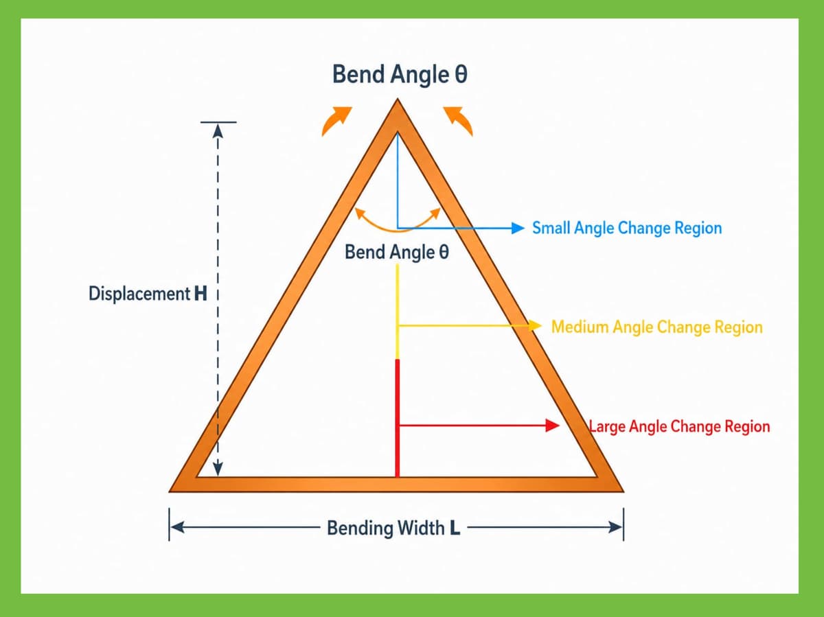
Let:
L = Effective bending width
H = Die displacement height
θ = Bending angle
Because the model is symmetrical, the geometry can be divided into two right triangles.
For one half of the geometry:
Horizontal length = L/2
Vertical length = H
Included angle = θ/2
According to the tangent relationship of a right triangle:
tan(θ/2) = L/(2H)
Therefore:
θ = 2 arctan[L/(2H)]
This is the fundamental equation used in the following analysis.
It shows that:
θ = f(H, L)
In other words, the bending angle θ is a function of both the die displacement H and the effective bending width L.
When L is fixed, the relationship becomes:
θ = f(H)
Therefore:
The bending angle is mathematically related to die displacement.
This is the basic geometric foundation of displacement-controlled busbar bending.
A note about the model
The equation above is based on an idealized geometric model.
Actual busbar bending is more complex and can be affected by material thickness, material properties, springback, die radius, die deformation, machine rigidity, mechanical clearances, and control-system characteristics.
These factors are intentionally not included in this mathematical model.
The purpose here is to isolate the basic geometric relationship between displacement and angle.
3. Why Displacement Error Cannot Be Simply Converted into Angle Error
A common question is:
If the die displacement has an error of 0.1 mm, how many degrees of angle error will this produce?
There is no universal answer.
The reason can be seen directly from:
θ = 2 arctan[L/(2H)]
The bending angle depends on both:
L
and:
H
Therefore, the same displacement change can produce different angular changes under different geometric conditions.
Even with the same bending width, the effect of a displacement change can vary at different positions.
Therefore, it is not technically rigorous to use a fixed conversion such as:
0.1 mm displacement error = X° angle error
without specifying the bending geometry and operating position.
The relationship must be calculated under the corresponding geometric conditions.
This is an important distinction when evaluating displacement-controlled busbar bending.
4. The Mathematical Influence of Die Width
The effective bending width L is an important variable in the geometric model.
From:
θ = 2 arctan[L/(2H)]
we can see that changing L changes the resulting angle even when H remains unchanged.
The influence becomes particularly obvious when we examine an extreme hypothetical case.
Suppose:
L = 0.1 mm
and:
H = 0.1 mm
Then:
θ = 2 arctan(0.1/0.2)
Therefore:
θ ≈ 53.13°
Now suppose the displacement height changes by:
ΔH = -0.05 mm
so that:
H = 0.05 mm
Then:
θ = 2 arctan(0.1/0.1)
Therefore:
θ = 90°
A displacement change of only:
0.05 mm
has therefore produced an angular change of approximately:
36.87°
The result appears extremely large.
However, this example requires an important clarification.
L = 0.1 mm is not a typical die width for actual busbar production.
It is an intentionally extreme mathematical example.
Its purpose is not to represent a practical production parameter, but to make the mathematical characteristics of the relationship visually and quantitatively obvious.
It demonstrates an important principle:
Angle error cannot be discussed independently of geometric scale.
When the characteristic geometric width becomes very small relative to the displacement change, the angular response can become extremely sensitive.
This is why a displacement error cannot be converted into a meaningful angle error without considering the geometry.
5. Fixing Die Width and Studying Displacement
We can now return to a more practical mathematical situation.
Let L remain constant and study only the effect of H.
The basic relationship remains:
θ = 2 arctan[L/(2H)]
From this equation:
When H increases, L/(2H) decreases, so θ decreases.
When H decreases, L/(2H) increases, so θ increases.
Therefore, within this idealized geometric model:
A smaller displacement height corresponds to a larger bending angle.
But this relationship alone does not tell us how sensitive the angle is to a small displacement change.
To answer that question, calculus becomes useful.
6. Using Calculus to Analyze Angular Sensitivity
Starting from:
θ = 2 arctan[L/(2H)]
we differentiate θ with respect to H.
The result is:
dθ/dH = -4L/(4H² + L²)
If we are interested only in the magnitude of the sensitivity:
|dθ/dH| = 4L/(4H² + L²)
This is a key result of the mathematical analysis.
It represents the local rate of change of bending angle with respect to die displacement.
In practical terms, it answers the question:
At a particular bending position, how much does the angle change when the die displacement changes by a small amount?
Therefore:
|dθ/dH| represents the local angular sensitivity to displacement.
7. Why Angular Sensitivity Changes with Bending Position
Consider:
|dθ/dH| = 4L/(4H² + L²)
When H is relatively large, the denominator becomes larger and the sensitivity becomes smaller.
When H becomes smaller, the denominator decreases and the sensitivity increases.
Therefore, within this idealized model:
The angular effect of a small displacement change varies with the bending position.
This leads to an important conclusion:
The same displacement error does not necessarily produce the same angle error at different bending positions.
This is not simply an empirical observation.
It follows directly from the mathematical relationship.
8. A Numerical Example with a 30 mm Bending Width
To make this relationship easier to understand, consider:
L = 30 mm
and a small displacement change of:
ΔH = 0.1 mm
First consider a bending angle of:
θ = 90°
From:
θ = 2 arctan[L/(2H)]
we obtain:
H = L/2 = 15 mm
At this position:
|dθ/dH| = 4L/(4H² + L²)
Substituting L = 30 mm and H = 15 mm gives:
|dθ/dH| ≈ 0.06667 rad/mm
Converting radians to degrees:
0.06667 × 180/π ≈ 3.82°/mm
Therefore, for a small displacement change of 0.1 mm:
|Δθ| ≈ |dθ/dH| × |ΔH|
giving:
|Δθ| ≈ 0.382°
Therefore:
Near 90°, a 0.1 mm displacement change corresponds to approximately 0.38° of angular change in this idealized model.
This is a local differential approximation.
For a larger displacement change, the original trigonometric equation should be used to calculate the actual difference between the two angles.
9. What Happens at a 120° Bending Angle?
Now keep:
L = 30 mm
and consider:
θ = 120°
From:
H = L/[2 tan(θ/2)]
we obtain:
H = 30/[2 tan(60°)]
Therefore:
H ≈ 8.66 mm
At this position:
|dθ/dH| = 4L/(4H² + L²)
which gives approximately:
|dθ/dH| ≈ 0.100 rad/mm
Converting to degrees:
0.100 × 180/π ≈ 5.73°/mm
Therefore, for:
ΔH = 0.1 mm
the local angular change is approximately:
|Δθ| ≈ 0.573°
We can now compare the two positions.
Near 90°:
0.1 mm displacement change → approximately 0.38° angular change
Near 120°:
0.1 mm displacement change → approximately 0.57° angular change
The same displacement change therefore produces different local angular changes at different bending positions.
This is one of the clearest mathematical reasons why angle accuracy cannot be treated as a fixed conversion from displacement accuracy.
10. From Angular Error Back to Displacement Error
The mathematical relationship can now be written in a more general form.
If the actual die displacement contains a small error:
ΔH
then the corresponding local angular change can be approximated by:
Δθ ≈ (dθ/dH) × ΔH
or, considering only the magnitude:
|Δθ| ≈ |dθ/dH| × |ΔH|
Substituting the derivative:
|Δθ| ≈ [4L/(4H² + L²)] × |ΔH|
This equation directly connects:
Displacement error → Local angular change
But it also reveals why the relationship is not a fixed conversion.
The result depends on:
L
and:
H
Therefore:
Angular error is a geometric result influenced by displacement error and the operating geometry.
11. Why Does Pure Mathematical Analysis Matter?
At this point, an important question arises:
Real busbar bending is much more complicated than a simple geometric model. Why is pure mathematical analysis useful?
The answer lies in separating a complex engineering problem into individual variables.
Actual busbar bending can be affected by:
Material thickness
Material hardness
Copper or aluminum properties
Elastic and plastic deformation
Material springback
Die geometry
Die wear
Die deformation
Machine structural rigidity
Mechanical clearances
Servo control accuracy
Displacement measurement accuracy
Other operating conditions
A complete engineering analysis must consider these factors.
However, if these factors have already been determined through testing, process experience, or calibration, they can temporarily be treated as fixed.
We can then ask a much simpler question:
Under otherwise unchanged conditions, what is the mathematical relationship between die displacement and bending angle?
This is the value of pure mathematical analysis.
It does not attempt to describe the entire physical process.
Instead, it isolates one fundamental relationship.
In simplified form:
Real engineering process:
Machine + Die + Material + Springback + Displacement + Geometry + Angle
can first be reduced to:
L + H → θ
and then further analyzed as:
ΔH → Δθ
This approach does not replace engineering.
It helps us understand the mathematical foundation within the engineering process.
12. What Mathematical Analysis Tells Us About Machine Precision
This leads to a more important engineering question.
Suppose that:
Material conditions are known
Springback characteristics are known
Die conditions are stable
Bending width is fixed
Other process variables remain unchanged
Then the theoretical relationship is:
θ = 2 arctan[L/(2H)]
If the actual machine displacement differs from the theoretical displacement by:
ΔH
the resulting local angular effect can be analyzed through:
Δθ ≈ (dθ/dH) × ΔH
The relationship can therefore be understood as:
Theoretical displacement→Actual displacement→Displacement error→Angular variation
This gives us another way to look at machine precision.
Instead of examining only the final angle, we can examine the displacement accuracy that produces that angle.
For a displacement-controlled three-station CNC busbar machine, this is particularly meaningful.
It helps explain why die displacement accuracy is an important fundamental parameter when evaluating the machine's bending performance.
This does not mean that displacement accuracy alone determines final bending accuracy.
It means that, when other factors are controlled or understood, displacement accuracy provides an important foundation for analyzing bending-angle stability.
13. Why Displacement Accuracy Deserves Attention
A specification such as:
Bending accuracy: ±0.5°
is easy to understand.
However, this number alone does not explain how the machine generates that angle.
From:
θ = 2 arctan[L/(2H)]
we know that the angle depends on the geometry and displacement.
From:
|dθ/dH| = 4L/(4H² + L²)
we know that the angular sensitivity to displacement changes with the operating position.
Therefore:
The same displacement error can produce different angular effects.
Conversely:
The same observed angle error does not necessarily indicate the same displacement-control capability.
This is why displacement accuracy deserves attention when evaluating a displacement-controlled three-station CNC busbar machine.
Angle accuracy remains important because the finished busbar must meet the required angle.
But from an engineering-analysis perspective:
Angle is the result.
Displacement is one of the fundamental variables that produces that result.
14. The Boundary Between Mathematical Analysis and Real Engineering
The mathematical model in this article is intentionally simplified.
This does not mean that real engineering factors are unimportant.
It means that the analysis first isolates the fundamental geometric relationship.
Real busbar bending can be viewed more broadly as:
Material → Die → Machine → Displacement → Deformation → Springback → Final angle
A complete engineering model therefore requires more than a trigonometric equation.
However, when the objective is to understand the basic relationship between displacement and angle, it is useful to temporarily fix or exclude other variables.
The analytical process can therefore proceed step by step:
Step 1: Establish the ideal geometric relationship.
Step 2: Analyze displacement and angle using trigonometry.
Step 3: Use calculus to analyze local sensitivity.
Step 4: Introduce material springback.
Step 5: Introduce mechanical and control errors.
Step 6: Develop a more complete engineering model.
In this sense, pure mathematical analysis is not separate from engineering.
It is a method of extracting and understanding the fundamental relationship within a complex engineering process.
15. From Trigonometry to Calculus
The mathematical development of displacement-controlled busbar bending can be summarized in four steps.
Step 1 — Geometric relationship
tan(θ/2) = L/(2H)
Step 2 — Angle as a function of displacement
θ = 2 arctan[L/(2H)]
Step 3 — Local sensitivity
dθ/dH = -4L/(4H² + L²)
or:
|dθ/dH| = 4L/(4H² + L²)
Step 4 — Local error relationship
|Δθ| ≈ |dθ/dH| × |ΔH|
This creates a clear mathematical progression:
Trigonometry describes the geometric relationship.
Calculus describes the rate of change.
Differential analysis connects displacement variation with local angular variation.
This is the mathematical significance of studying displacement-controlled busbar bending.
16. What This Means for Displacement-Controlled Three-Station CNC Busbar Machines
For a three-station CNC busbar machine using displacement detection, the control system is fundamentally concerned with the position or displacement of the moving mechanism.
The simplified control process can be represented as:
Target displacement → Mechanical movement → Displacement detection → Feedback → Position correction
The bending process can then be represented as:
Displacement → Geometric deformation → Bending angle
Therefore, when displacement detection, servo positioning, mechanical transmission, and machine rigidity provide sufficient accuracy and stability, the difference between theoretical and actual displacement can be controlled more effectively.
Under otherwise stable process conditions, this contributes to more consistent bending-angle results.
However, the distinction remains important:
Displacement accuracy is not another name for final angle accuracy.
Rather:
For a displacement-controlled three-station CNC busbar bending system, displacement accuracy is an important fundamental variable for analyzing and controlling bending-angle stability.
This is the more rigorous engineering interpretation.
17. Rethinking Precision in Three-Station CNC Busbar Bending
The mathematical analysis above leads to several conclusions.
First, three-station busbar bending can be understood as an indirect bending process when the bending angle is generated through controlled linear die displacement rather than directly controlled rotational motion.
Second, the bending angle is a function of both displacement and bending width:
θ = 2 arctan[L/(2H)]
Third, there is no universal fixed conversion between displacement error and angle error.
The relationship depends on:
L and H
Fourth, calculus allows us to analyze the local sensitivity of the bending angle to a small displacement change:
|dθ/dH| = 4L/(4H² + L²)
Fifth, the same displacement error can produce different angular effects at different bending positions.
These conclusions are not simply based on practical experience.
They can be derived directly from the mathematical model.
18. Conclusion: From the Angle Back to the Displacement
The final result of busbar bending is an angle.
But if we ask a deeper question:
How is that angle generated?
The mathematical relationship provides a clear starting point.
From:
tan(θ/2) = L/(2H)
we obtain:
θ = 2 arctan[L/(2H)]
Through calculus, we then obtain:
dθ/dH = -4L/(4H² + L²)
This allows us to understand not only that displacement affects angle, but also that the sensitivity of angle to displacement varies with the geometric condition.
This is the significance of pure mathematical analysis.
It does not replace material testing.
It does not replace engineering experience.
It does not replace machine calibration.
Instead, it provides a way to isolate and understand a fundamental geometric relationship within a much more complicated industrial process.
When material springback, die conditions, and other practical factors have been determined, this mathematical relationship can help us analyze how displacement accuracy contributes to bending-angle stability.
For displacement-controlled three-station CNC busbar machines, therefore, it may be more meaningful to ask not only:
“What angle accuracy can this machine achieve?”
but also:
“What is the actual displacement accuracy of the machine?”
and:
“Under what geometric conditions does this displacement accuracy produce a particular angular variation?”
These questions allow us to look beyond the final angle and examine the mechanism that produces it.
For Bailipower, technical research is not simply about explaining how a busbar machine bends.
It is also about helping customers understand the engineering principles behind the machine.
From the angle, we see the result.
From displacement, we see the process.
Through mathematics, we see the fundamental precision of the machine.
19. FAQ
19.1 Is the bending angle directly controlled by a three-station CNC busbar machine?
Not directly. In a three-station CNC busbar machine using displacement detection and displacement control, the bending die primarily moves in a linear direction. The final bending angle is generated indirectly through the geometric relationship between die displacement and the busbar.
Therefore, this process can be understood as an indirect bending process.
19.2 What is the mathematical relationship between die displacement and busbar bending angle?
In an idealized symmetric geometric model, where L represents the effective bending width, H represents the die displacement height, and θ represents the bending angle:
tan(θ/2) = L/(2H)
Therefore:
θ = 2 arctan[L/(2H)]
This shows that the bending angle is a function of displacement and bending geometry.
19.3 Why can the same displacement error produce different angle errors?
Because bending angle depends not only on displacement but also on the bending geometry. In addition, the sensitivity of angle to displacement changes according to the die position.
Using calculus:
dθ/dH = -4L/(4H² + L²)
Therefore, the same displacement change can produce different angular changes under different bending conditions.
19.4 Why does die width affect bending-angle sensitivity?
From:
θ = 2 arctan[L/(2H)]
we can see that the effective bending width L directly affects the bending angle.
Therefore, displacement error cannot be converted into a fixed angle error without considering the corresponding geometry. Under certain conditions, a smaller effective bending width can make the angular response more sensitive to displacement changes.
19.5 Why is pure mathematical analysis useful for busbar bending?
Pure mathematical analysis allows us to temporarily fix practical factors such as material springback and die conditions, and isolate the fundamental geometric relationship between displacement and bending angle.
It helps us understand the process as:
Displacement → Geometric deformation → Bending angle
Mathematical analysis does not replace practical process testing. Instead, it provides a clearer way to understand the fundamental working principle and precision characteristics of a three-station CNC busbar machine.
19.6 Is displacement accuracy the same as final bending-angle accuracy?
No.
Displacement accuracy is an important fundamental factor affecting bending-angle stability, but the final angle can also be influenced by material springback, material properties, die conditions, machine rigidity, and other process variables.
A more rigorous statement is:
For a displacement-controlled three-station CNC busbar machine, displacement accuracy is an important fundamental parameter for analyzing and controlling bending-angle stability.