Previous
Next
Three-Foil Simultaneous Foil Winding Machine PFW-600
A Three-Foil Synchronous Winding Solution for Transformer and Reactor Coil Manufacturing
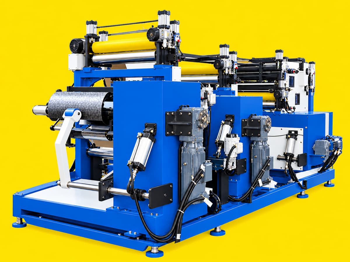
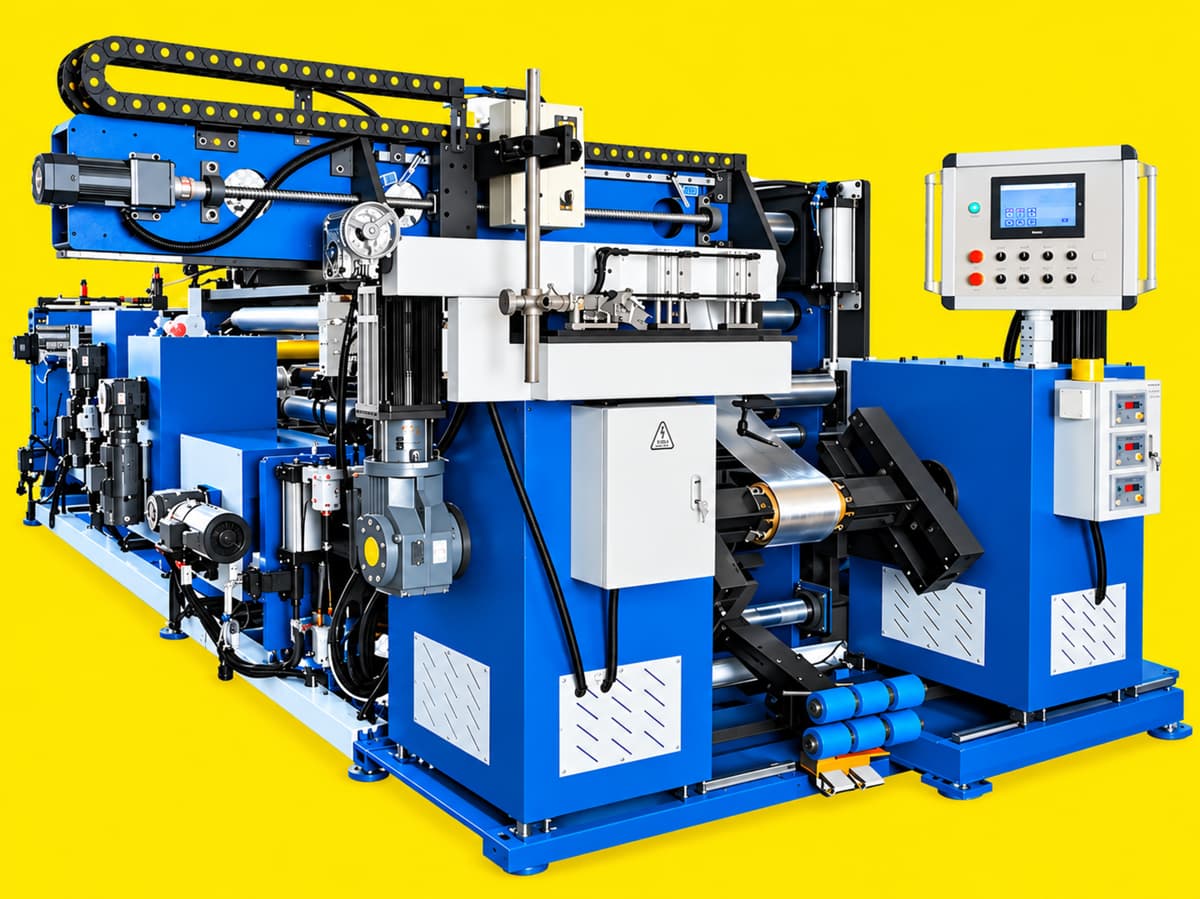
PFW-600 Three-Foil Simultaneous Foil Winding Machine is designed for the simultaneous winding of three foil conductors to form a three-layer parallel winding. It is suitable for the automated production of foil coils for dry-type transformers, oil-immersed transformers, and reactors.
PFW-600 is an industrial foil coil winding machine developed by Bailipower for manufacturers of transformers, reactors, and other electrical equipment. It is suitable for winding copper and aluminum foil coils.
The machine is equipped with three independent unwinding units, allowing three foil conductors to be fed and wound simultaneously. Depending on the selected configuration, it can also be equipped with independent servo-driven edge correction, tension control, foil leveling, deburring, dust removal, welding, and cutting functions.
For winding processes that require three foil conductors to be wound simultaneously, this configuration can help reduce separate winding operations and improve production efficiency. Its suitability should be evaluated according to the coil design, conductor materials, insulation arrangement, and manufacturing process.
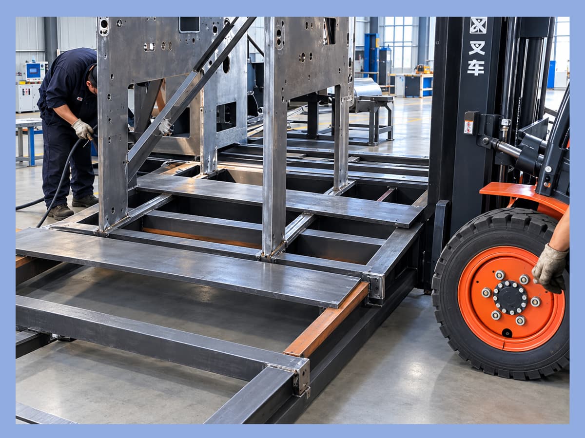
Bailipower designs machinery based on actual production requirements, with mechanical structures, control systems, and manufacturing processes working together in a practical and reliable way.
1. Main Technical Specifications
| Item | Specification |
|---|---|
| Machine Model | PFW-600 |
| Machine Type | Three-Foil Simultaneous Foil Winding Machine |
| Conductor Materials | Copper Foil, Aluminum Foil |
| Foil Width | 100–600 mm |
| Copper Foil Thickness | 0.3–2.0 mm |
| Aluminum Foil Thickness | 0.5–2.5 mm |
| Finished Coil Inner Diameter | Φ130–Φ500 mm |
| Maximum Finished Coil Outer Diameter | Φ800 mm |
| Winding Configuration | Three-Foil Simultaneous Winding |
| Main Spindle Speed | 0–20 rpm, stepless speed control |
| Rated Main Spindle Output Torque | 5,000 N·m |
| Constant Tension Control Accuracy | ±5% |
| Turn Counting Accuracy | ±0.1 turn |
| Unwinding Core Inner Diameter | Φ460 / Φ500 mm |
| Maximum Unwinding Roll Diameter | Φ1,000 mm |
| Maximum Load per Unwinding Shaft | Approx. 1,000 kg |
| Maximum Tension per Foil Path | 4,500–6,000 N (optional, depending on configuration) |
| Unwinding Edge Correction Accuracy | ≤ ±0.5 mm |
| Main Spindle Center Height | 1,050 mm |
| Power Supply | 380 V / 50 Hz / 3-phase |
| Main Machine Installed Power | 31 kW (excluding external welding power source) |
| Compressed Air Pressure | 0.5–0.6 MPa |
| Recommended Air Supply Capacity | 1.5 m³/min |
| Overall Dimensions (L × W × H) | 7,200 × 3,800 × 2,400 mm |
| Main Machine Weight | Approx. 6,800 kg |
Note: The specifications above are provided for reference. Some functions and performance capabilities depend on the selected machine configuration. Final specifications are subject to the confirmed technical agreement. The external welding power source is not included in the main machine installed power.
2. Three-Foil, Two-Foil, and Single-Foil Winding Configurations
Transformer and reactor coils vary in conductor arrangement, insulation structure, and manufacturing process. Therefore, not every foil coil is suitable for the same winding configuration.
In addition to the PFW-600 three-foil simultaneous winding machine featured on this page, Bailipower can provide two-foil simultaneous winding machines and single-foil winding machines according to customers' production requirements and coil designs.
2.1 Three-Foil Simultaneous Winding
Designed for winding processes that require three foil conductors to be wound simultaneously. When the coil structure and manufacturing process are suitable, this configuration can reduce separate winding operations and improve production efficiency.
2.2 Two-Foil Simultaneous Winding
Suitable for coil structures that require two foil conductors to be wound simultaneously. A corresponding two-foil configuration can be selected for products whose conductor arrangement and manufacturing process support simultaneous winding.
2.3 Single-Foil Winding
Suitable for conventional winding processes in which one foil conductor is wound at a time. The machine configuration can be selected according to the coil structure and processing requirements.
The appropriate winding configuration should be determined by the coil design, conductor materials, insulation arrangement, winding process, and production requirements. Bailipower can evaluate the required machine configuration based on customers' coil drawings and manufacturing processes.
This page focuses on the PFW-600 Three-Foil Simultaneous Foil Winding Machine. Two-foil and single-foil winding solutions are available as separate machine configurations and should not be understood as functions that can be switched on the standard PFW-600 without modification.
3. Applications
PFW-600 is designed for electrical equipment manufacturers and can be used for foil coil production in applications such as:
Low-voltage foil windings for dry-type transformers
Foil windings for oil-immersed transformers
Reactor foil coils
Other suitable coils made from copper or aluminum foil
Depending on the coil design and machine configuration, the machine can process round, oval, and rectangular coil shapes.
When selecting a machine, customers are advised to provide information about conductor materials, foil width and thickness, finished coil inner and outer diameters, axial dimensions, insulation structure, and required production cycle. This information helps determine whether the PFW-600 is suitable for the intended application.
4. Three Independent Unwinding Units and Automatic Edge Correction
PFW-600 is equipped with three independent unwinding units. Each unit can be configured to handle the corresponding foil conductor and layer insulation material.
Main features include:
Three independent unwinding units for simultaneous feeding of three foil conductors.
Servo-driven photoelectric edge correction to help maintain the lateral position of the foil during feeding.
Adjustable unwinding tension according to the manufacturing process.
Unwinding configurations selected according to material specifications and production requirements.
The reference edge correction accuracy is ≤ ±0.5 mm. Actual processing results may also be affected by foil edge condition, material flatness, tension variations, machine adjustment, and operating conditions.
5. Tension Control and Main Spindle Winding
Foil tension and main spindle movement directly affect material feeding and coil formation during the winding process.
PFW-600 uses servo-driven main spindles combined with unwinding tension control to coordinate winding speed and foil feeding.
Main specifications and functions include:
Main spindle servo motors: 5.5 kW × 2
Rated main spindle output torque: 5,000 N·m
Main spindle speed: 0–20 rpm, stepless speed control
Constant tension control accuracy: ±5%
Turn counting accuracy: ±0.1 turn
Finished coil inner diameter: Φ130–Φ500 mm
Maximum finished coil outer diameter: Φ800 mm
Winding speed can be adjusted according to coil structure, material characteristics, and process requirements. Appropriate tension and speed settings at different winding stages help improve winding stability.
It is important to distinguish tension control accuracy and turn counting accuracy from the final quality of the finished coil. The actual coil quality is also influenced by conductor flatness, insulation material condition, welding quality, and process parameters.
6. Foil Leveling, Deburring, and Dust Removal
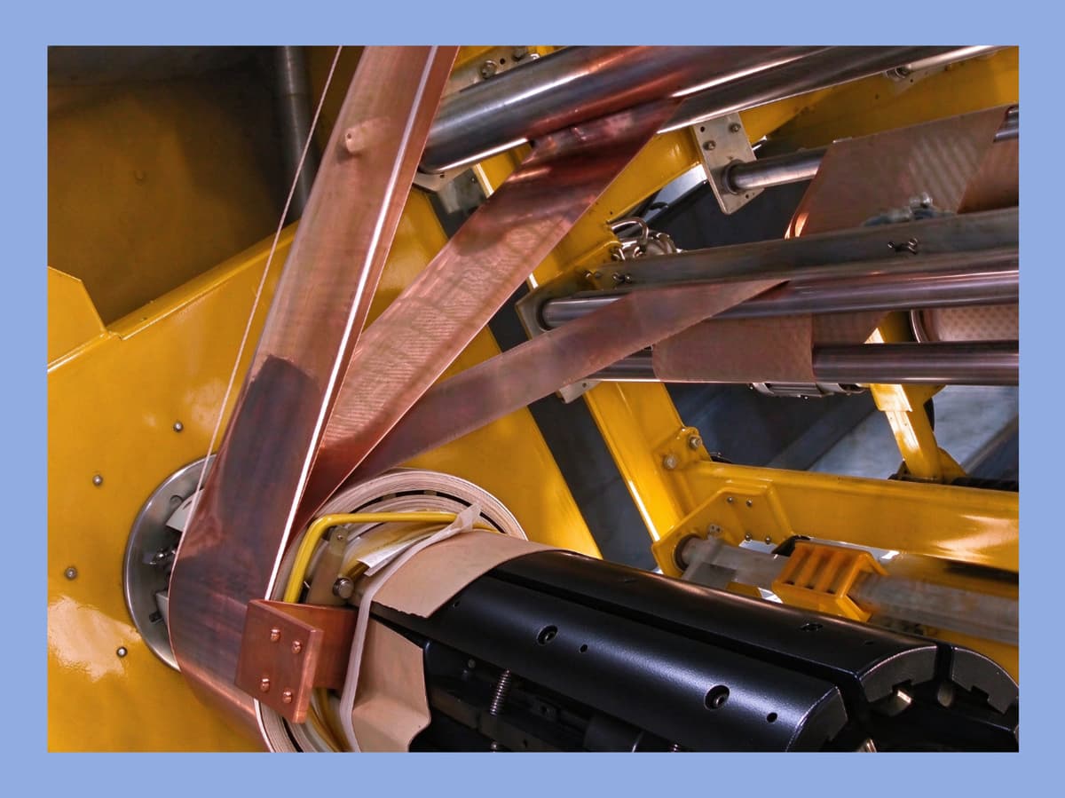
The surface and edge condition of foil materials can affect the subsequent winding process. Depending on the selected configuration, PFW-600 can be equipped with foil leveling, deburring, and dust removal units.
6.1 Foil Leveling
Upper and lower pressure rollers are used to level the foil before it enters the winding area. Pneumatic pressure is applied to the rollers, with the pressure adjusted according to foil thickness and process requirements.
6.2 Deburring
Circular blades or brushes can be selected to process foil edges and help reduce the potential effects of burrs on winding and insulation assembly.
6.3 Dust Removal
An electrostatic and brush-based dust removal system can be used to clean particles and other contaminants from the foil surface. The actual cleaning result depends on material surface conditions, the working environment, and machine configuration.
These auxiliary units help improve foil condition before winding. They do not replace proper raw material quality control, tool maintenance, or process management.
7. Welding Methods and Configuration Options
The conductor joining method used in foil coil manufacturing should be selected according to material type, thickness, coil structure, and process requirements.
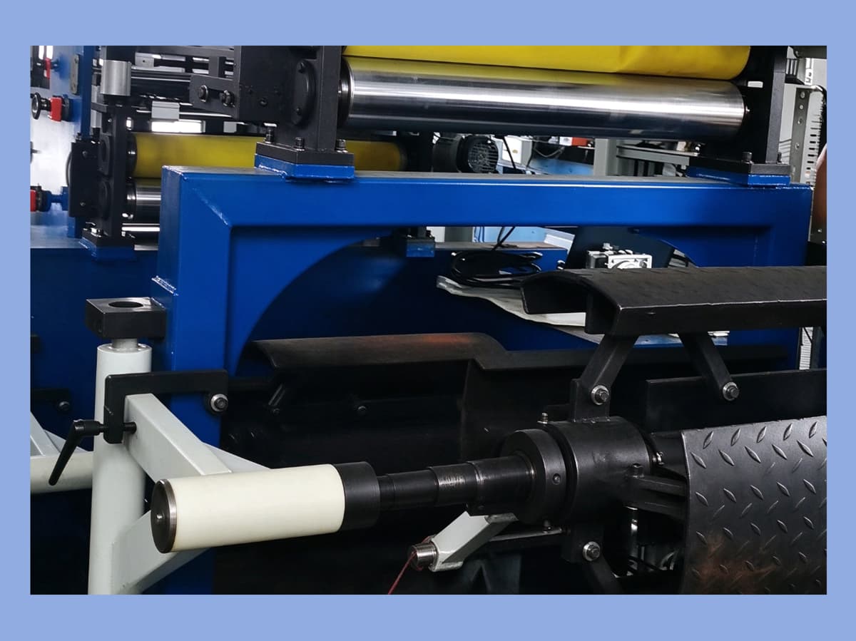
Depending on customer requirements, PFW-600 can be configured with suitable welding solutions, such as TIG welding or cold pressure welding. The appropriate method should be confirmed during machine selection based on the conductor material and joining process.
Welding-related configurations may include:
The corresponding welding mechanism and movement unit
Welding position adjustment and motion control
An external welding power source or related equipment suitable for the selected welding process
The model, rated specifications, and material compatibility of the external welding power source should be determined according to the final welding process. The external welding power source is not included in the PFW-600 main machine installed power of 31 kW.
For copper foil and other conductive materials, customers are advised to provide foil thickness, joint position, and the intended welding method before confirming the machine configuration.
8. Cutting Unit
PFW-600 can be equipped with a motor-driven, screw-feed circular disc cutting unit for cutting foil after the winding process.
The cutting unit uses a motor-driven screw mechanism. The reference cutting traverse speed is approximately 1.5 m/min. Actual cutting results depend on foil thickness, material characteristics, blade condition, and machine adjustment.
The cutting capability and configuration should be confirmed according to the copper or aluminum foil specifications used by the customer.
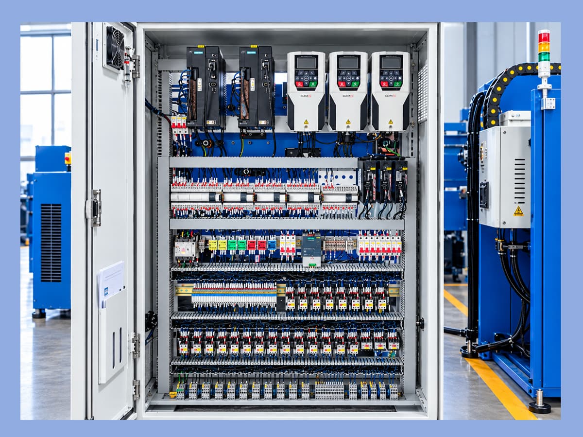
9. Electrical Control System
PFW-600 can be equipped with a PLC control system, touchscreen, operating buttons, and corresponding drive units to coordinate the main machine operations.
The standard configuration uses a XINJE PLC. Siemens and other control system brands are available as options according to customer requirements. The main spindle and related motion axes can use servo drives depending on the selected configuration.
At Bailipower, we believe that the control system should serve the actual manufacturing process rather than simply increase system complexity. A practical control solution should balance operating convenience, process requirements, maintenance conditions, and the working environment.
The final PLC brand, number of controlled axes, functions, and electrical configuration are subject to the confirmed technical proposal.
10. Installation Requirements
Before installing the PFW-600, customers are advised to check the following site requirements:
Power supply: 380 V / 50 Hz / 3-phase.
Main machine installed power: 31 kW, excluding the external welding power source.
Compressed air: Working pressure of 0.5–0.6 MPa, with a recommended air supply capacity of 1.5 m³/min.
Installation space: The main machine dimensions are approximately 7,200 × 3,800 × 2,400 mm. Additional space should be reserved for operation, maintenance, material loading, and material handling.
Lifting and transportation: The main machine weighs approximately 6,800 kg. Transportation and installation arrangements should take account of access routes, floor load capacity, and lifting conditions.
If an external welding power source or other optional equipment is included, additional installation space and suitable power connections should also be provided.
Bailipower — Helping You Choose the Right Machine and Use It Better.
11. Frequently Asked Questions
11.1 What is the PFW-600?
PFW-600 is a Three-Foil Simultaneous Foil Winding Machine developed by Bailipower. It is designed to wind three foil conductors simultaneously to form a three-layer parallel winding. Equipped with independent edge correction and tension control systems, it is intended for automated foil coil production in transformer and reactor manufacturing.
11.2 What industries is the PFW-600 suitable for?
The machine is mainly intended for manufacturers of transformers, reactors, and other electrical equipment. It can be used to wind suitable copper or aluminum foil coils. Actual suitability depends on the coil design and manufacturing process.
11.3 Can the PFW-600 process both copper foil and aluminum foil?
Yes. The reference processing ranges are 0.3–2.0 mm for copper foil and 0.5–2.5 mm for aluminum foil, with foil widths from 100 to 600 mm. Material condition and specific process requirements should be confirmed during machine selection.
11.4 What does three-foil simultaneous winding mean?
Three-foil simultaneous winding means that three separate foil conductors are wound at the same time. This is different from winding one foil conductor into three successive layers. Whether this method is suitable depends on the coil structure and actual manufacturing process.
11.5 Does Bailipower provide two-foil and single-foil winding machines?
Yes. Bailipower can provide two-foil simultaneous winding machines and single-foil winding machines according to customers' coil structures, conductor arrangements, and manufacturing requirements. The specific machine model and configuration should be confirmed separately.
11.6 Is the welding power source included with the machine?
The welding solution can be selected according to the manufacturing process. The model and specifications of the external welding power source should be confirmed in the technical proposal. It is not included in the main machine installed power of 31 kW.
11.7 How can I determine whether the PFW-600 is suitable for my products?
Customers are advised to provide coil drawings or key dimensions, together with information about conductor materials, foil width and thickness, coil inner and outer diameters, insulation structure, joining method, and target production cycle. Bailipower can use this information to evaluate the machine specifications and configuration.