Previous
Next
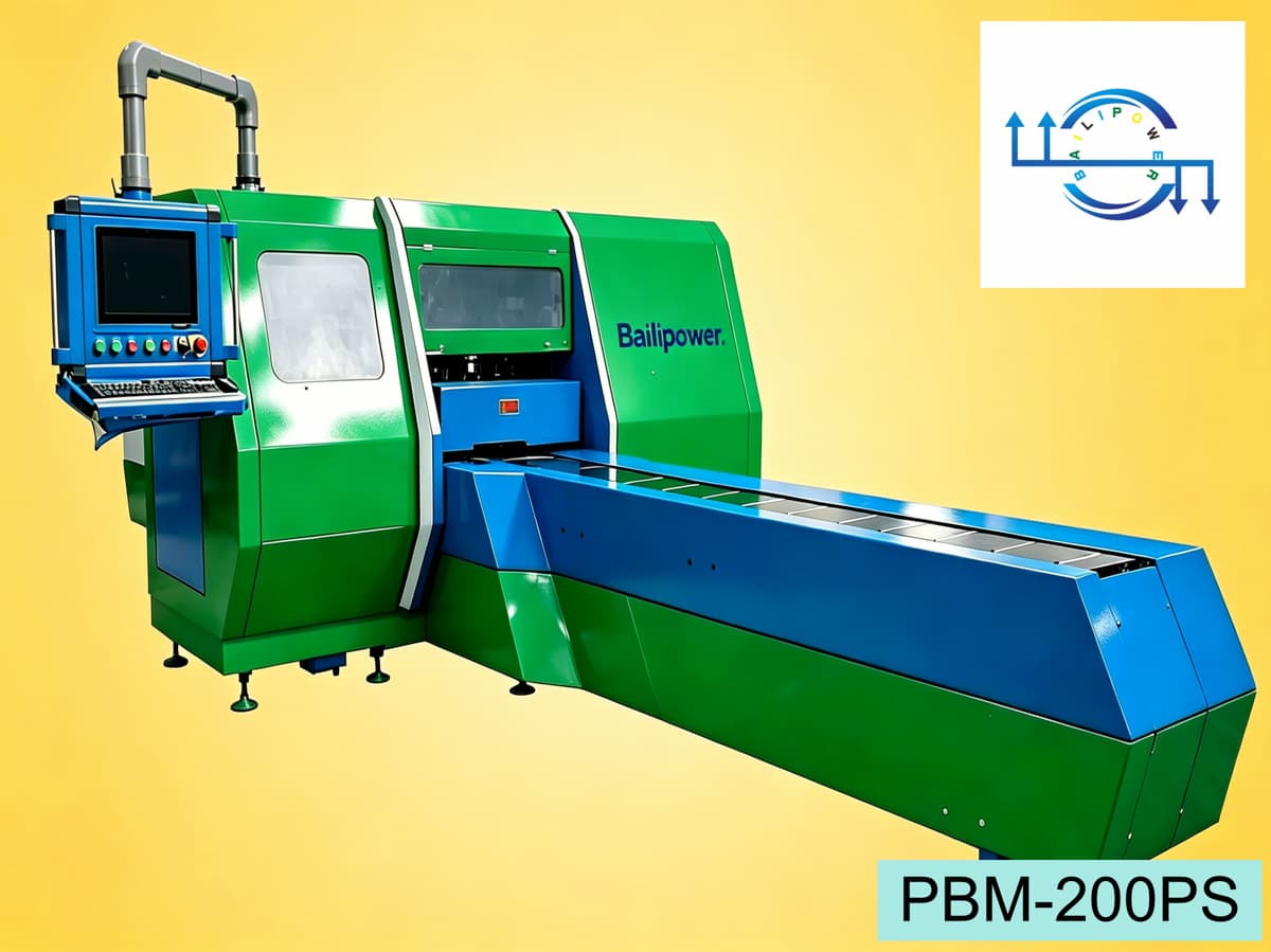
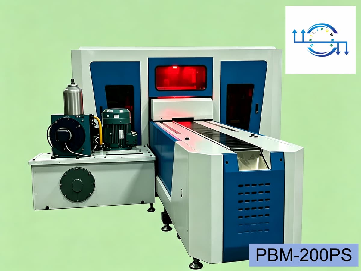
CNC Busbar Punching and Shearing Line PBM-200PS
More Than a Machine — A Complete Busbar Processing Solution
Bailipower PBM-200PS CNC Busbar Punching and Shearing Line has been developed specifically for the automatic processing of copper and aluminium busbars.
Unlike conventional product pages that focus only on specifications, the PBM series has been designed to help customers understand not only what the machine can do, but also why it has been designed in this way.
At Bailipower, we believe that a good machine should be reliable, understandable, easy to maintain, and easy to operate.
1. What Does PBM-200PS Mean?
PBM — Power Busbar Machine
PBM stands for Power Busbar Machine, which represents the Bailipower busbar processing equipment series.
Power refers to the electrical power industry.
Busbar refers to copper and aluminium busbars.
Machine refers to CNC processing equipment.
200 — Maximum Processing Width
The number 200 indicates the maximum busbar width of 200 mm.
Examples:
| Model | Maximum Width |
|---|---|
| PBM-160PS | 160 mm |
| PBM-200PS | 200 mm |
| PBM-250PS | 250 mm |
| PBM-300PS | 300 mm |
PS — Punching and Shearing
PS represents the machine's core functions:
Punching
Shearing
Embossing remains part of the standard configuration.
For Bailipower, a good model designation is more than just a name. It is a clear, consistent, and easy-to-understand product language.
We hope that our customers will not only remember the PBM-200PS, but also quickly understand the machine's positioning, processing capabilities, and relationship to other models within the series simply by reading its designation. In this way, customers can more easily select the machine that best suits their requirements.
2. Main Applications
The PBM-200PS is designed primarily for the processing of copper and aluminium busbars.
Typical applications include:
Switchgear manufacturing
Transformer manufacturing
Busbar trunking systems
Electrical distribution equipment
Renewable energy equipment
3. Available Processes
The machine can perform:
Round-hole punching
Slotted-hole punching
Embossing
Shearing
Optional functions:
Corner rounding
Slotting
4. Six Servo Axes Explained
What truly distinguishes Bailipower is not simply higher specifications, but the ability to make complex equipment easier to understand.
First, let’s clarify: What is a servo axis?
For the PBM-200PS, one servo axis refers to an independent motion unit controlled by one set of servo drive plus one servo motor. The motion can be linear or rotary. In other words, an "axis" represents an independently controllable movement, not merely the traditional X, Y, Z coordinate axes.
Unified Naming Standard
For all PBM series, clamps are defined following the natural processing flow of the workpiece. Along the feeding direction, the first clamp is designated Clamp 1, and the second one Clamp 2.
This naming rule is independent of equipment installation orientation and on-site layout. It is solely based on the workpiece flow. A consistent technical terminology is adopted throughout design, programming, operation and after-sales service to avoid confusion.
X1 Axis — Clamp 1 Positioning Axis
Main functions:
Feeding
Positioning
Coordination with Clamp 2
Maximum travel:
2000 mm
X2 Axis — Clamp 2 Positioning Axis
Main functions:
feeding
Positioning
Coordination with Clamp 1
Maximum travel:
1000 mm
C1 Axis — Clamp 1 Clamping Axis
Main functions:
Clamping
Releasing
C2 Axis — Clamp 2 Clamping Axis
Main functions:
Clamping
Releasing
Y Axis — Tool Magazine Positioning Axis
Main functions:
Tool selection
Automatic positioning
Process switching
Maximum travel:
700 mm
Z Axis — Pressing Unit Positioning Axis
Main functions:
Vertical positioning of the pressing unit before processing operations.
Maximum travel:
350 mm
5. Control System
Standard configuration:
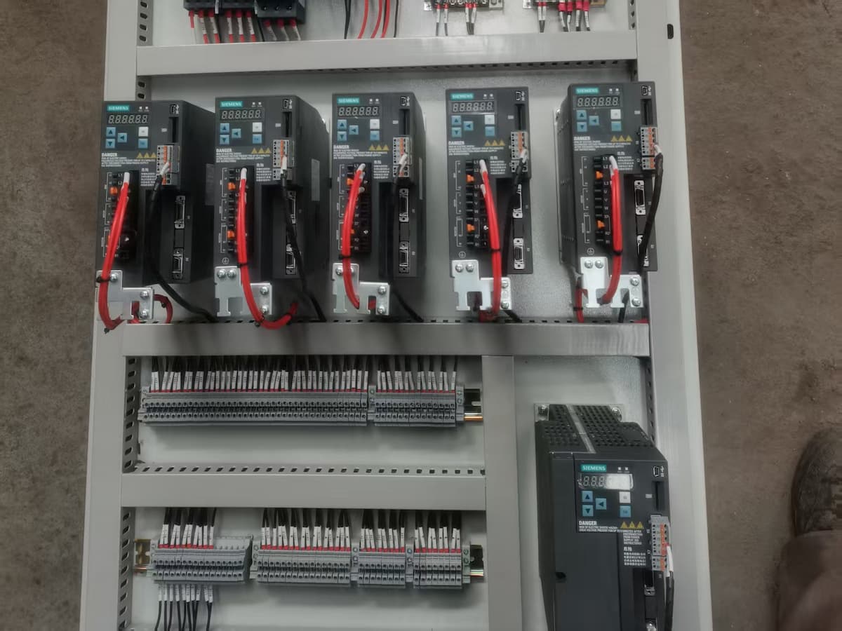
Siemens PLC
Siemens servo system
Alternative brands are available upon request.
6. Automatic Lubrication System
An independent lubrication pump automatically supplies lubricant to the moving components according to predefined intervals.
This reduces maintenance requirements and extends the service life of the machine.
7. Technical Specifications
Why do we explain every parameter in detail?
At Bailipower, we believe that technical specifications should do more than present numbers. Every parameter should help customers understand how the machine works, how it is designed, and how it can best meet their production requirements.
7.1 General Information
| Item | Specification |
|---|---|
| Model | PBM-200PS |
| Brand | Bailipower |
| Product Name | CNC Busbar Punching and Shearing Line |
| Main Processes | Punching, Shearing, Embossing |
| Standard Tool Configuration | 6 Punching Dies, 1 Shearing Die, 1 Embossing Die |
| Number of Servo Axes | 6 |
7.2 Processing Capability
| Item | Specification |
|---|---|
| Main Materials | Copper Busbars, Aluminium Busbars |
| Maximum Workpiece Length | 6000 mm |
| Maximum Workpiece Width | 200 mm |
| Maximum Workpiece Thickness | 16 mm |
| Minimum Workpiece Size | 15 × 3 mm |
| Punching Diameter Range | Ø4.3–Ø35 mm |
| Maximum Embossing Area | 200 × 50 mm |
| Longitudinal Hole Pitch Accuracy | ±0.20 mm |
7.3 Workpiece Feeding and Positioning System
| Item | Specification |
|---|---|
| Conveyor Motor Power | 0.75 kW |
| Clamp 1 (X1 Axis) Maximum Effective Travel | 2000 mm |
| Clamp 2 (X2 Axis) Maximum Effective Travel | 1000 mm |
| Maximum Positioning Speed of Clamp 1 and Clamp 2 | 60 m/min |
| X1 and X2 Axis Positioning Accuracy | ±0.10 mm / 1000 mm |
| X1 and X2 Axis Repeatability Accuracy | ±0.05 mm |
7.4 Tool Magazine System
| Item | Specification |
|---|---|
| Tool Magazine (Y Axis) Maximum Effective Travel | 700 mm |
| Tool Magazine (Y Axis) Maximum Positioning Speed | 40 m/min |
| Y Axis Positioning Accuracy | ±0.10 mm / 1000 mm |
| Y Axis Repeatability Accuracy | ±0.05 mm |
7.5 Pressing Unit
| Item | Specification |
|---|---|
| Nominal Force | 600 kN |
| Hydraulic Cylinder Stroke | 45 mm |
| Maximum Pressing Frequency | 150 strokes/min |
| Pressing Unit (Z Axis) Maximum Positioning Travel | 350 mm |
| Z Axis Maximum Positioning Speed | 40 m/min |
| Z Axis Positioning Accuracy | ±0.10 mm / 1000 mm |
| Z Axis Repeatability Accuracy | ±0.05 mm |
7.6 Power System
| Item | Specification |
|---|---|
| Hydraulic Station Motor Power | 15 kW |
| Conveyor Motor Power | 0.75 kW |
| Lubrication System | Independent Automatic Lubrication System |
| Total Installed Power | 21 kW |
7.7 Control System
| Item | Specification |
|---|---|
| Standard Control Configuration | Siemens PLC + Siemens Servo System |
| Optional Control Brands | Mitsubishi, Schneider, Delta, or Equivalent |
7.8 Dimensions and Weight
| Item | Specification |
|---|---|
| Overall Dimensions (L × W × H) | Approximately 7500 × 2980 × 1750 mm |
| Net Weight | Approximately 7600 kg |
| Power Supply | Customised According to Local Standards |
8. Frequently Asked Questions
8.1 What does PBM-200PS mean?
PBM stands for Power Busbar Machine, which is the product series name used by Bailipower.
200 represents the maximum processing width of 200 mm.
PS stands for Punching and Shearing, the machine's two primary functions.
The standard configuration also includes an embossing function.
8.2 Why is the PBM-200PS called a punching and shearing line rather than a punching machine?
The PBM-200PS is more than a single machine. It integrates material feeding, positioning, tool selection, punching, shearing, embossing, and unloading into one complete processing system.
Therefore, the term CNC Busbar Punching and Shearing Line more accurately reflects the machine's structure and operating principles.
8.3 Why does the PBM-200PS use six servo axes?
Each servo axis performs a specific function.
| Axis | Function |
|---|---|
| X1 | Clamp 1 positioning |
| X2 | Clamp 2 positioning |
| C1 | Clamp 1 clamping |
| C2 | Clamp 2 clamping |
| Y | Tool magazine positioning |
| Z | Pressing unit vertical positioning |
Together, these six axes enable automatic feeding, positioning, tool selection, and processing.
8.4 How are Clamp 1 and Clamp 2 defined?
The PBM series defines the clamps according to the natural flow direction of the workpiece.
The first clamp is defined as Clamp 1.
The second clamp is defined as Clamp 2.
This naming method remains consistent regardless of machine orientation or installation layout.
8.5 Why are two clamps used instead of one?
A single clamp can only move the workpiece within its own travel range.
The dual-clamp system allows long workpieces to be processed continuously through coordinated movements of Clamp 1 and Clamp 2.
This design improves positioning accuracy, processing efficiency, and operational stability.
8.6 Does the Z axis perform the punching operation?
No.
The Z axis is responsible only for the vertical positioning of the pressing unit before processing begins.
The actual punching, shearing, and embossing forces are generated by the hydraulic cylinder.
The processing sequence is as follows:
Z-axis positioning→Hydraulic cylinder downward stroke→Punching / Shearing / Embossing→Hydraulic cylinder return stroke